
Anti-condensation cabinet plate structure for electric control cabinet

An electric control cabinet and anti-condensation technology, which is applied in the direction of substation/power distribution device shell, etc., can solve the problems that the electric control cabinet is easy to generate condensation or water droplets, affect the normal operation of electrical equipment, and damage electrical equipment, so as to speed up condensation. The speed of dew elimination, reasonable design, and the effect of ensuring normal operation

Pending Publication Date: 2021-12-07
苏州华龙大金电加工机床有限公司
View PDF0 Cites 0 Cited by
  • Summary
  • Abstract
  • Description
  • Claims
  • Application Information

AI Technical Summary

Problems solved by technology

[0003] The existing electric control cabinet usually operates in a high temperature and humid environment, especially during the southern sky or the rainy season, condensation or water droplets are easily generated in the electric control cabinet. As we all know, all the electric control cabinets are installed Equipment or devices, once these electrical appliances are exposed to water, they are prone to short circuit, affecting the normal operation of the electrical equipment controlled by them, and even damaging related electrical equipment

Method used


Image

  • Anti-condensation cabinet plate structure for electric control cabinet
  • Anti-condensation cabinet plate structure for electric control cabinet
  • Anti-condensation cabinet plate structure for electric control cabinet

Examples


Embodiment Construction

[0017] The following will clearly and completely describe the technical solutions in the embodiments of the present invention with reference to the accompanying drawings in the embodiments of the present invention. Obviously, the described embodiments are only some, not all, embodiments of the present invention. Based on the embodiments of the present invention, all other embodiments obtained by persons of ordinary skill in the art without making creative efforts belong to the protection scope of the present invention.

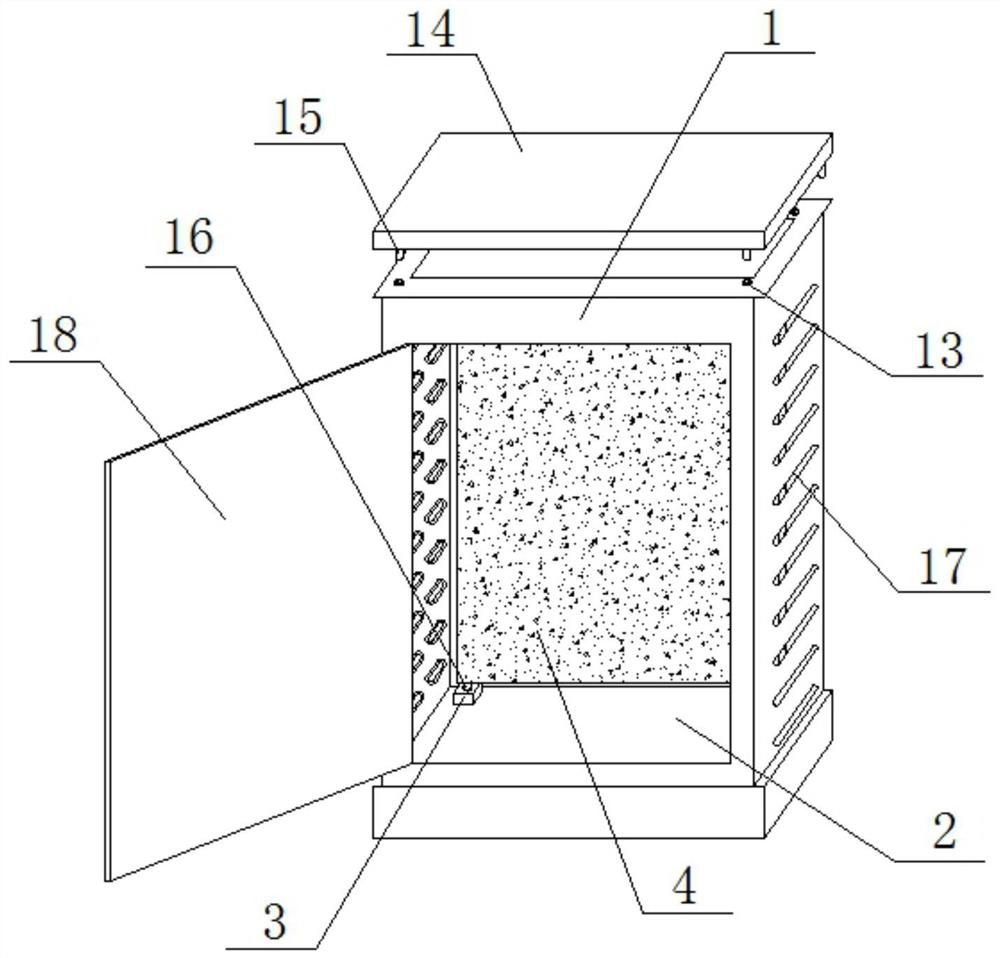
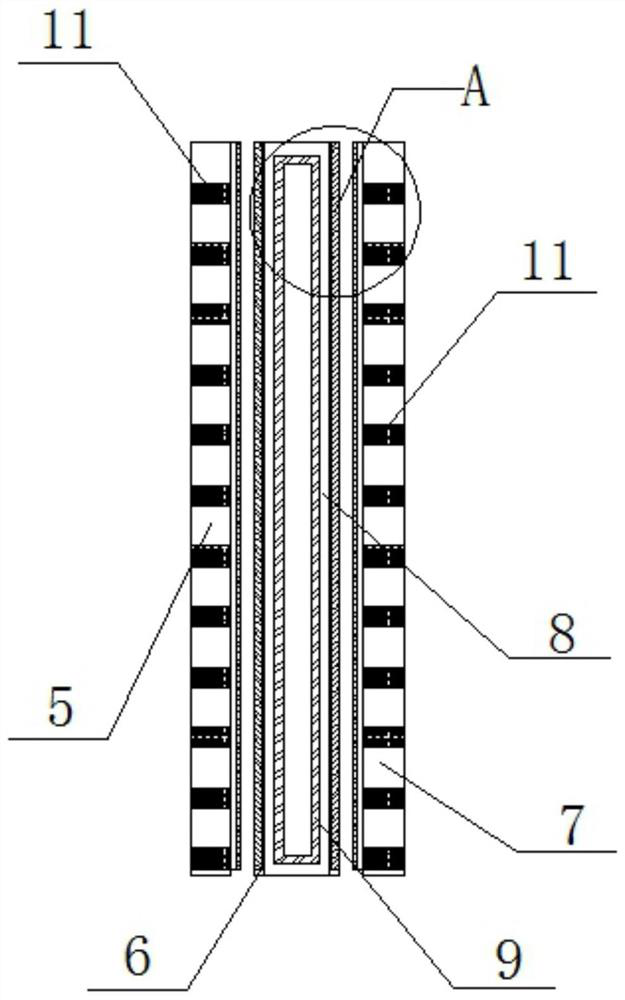
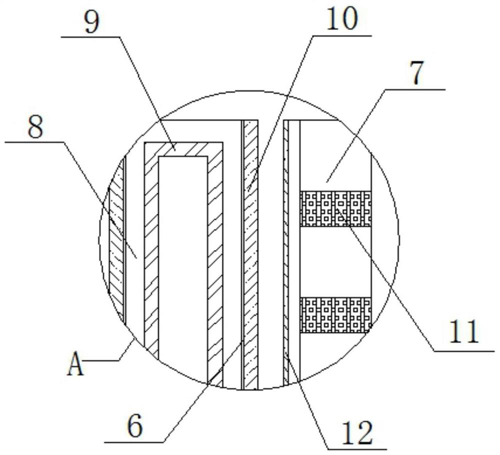
[0018] see Figure 1-3 , the present invention provides a technical solution: an anti-condensation cabinet 4 structure for an electric control cabinet, including a cabinet body 1 of the electric control cabinet, a cavity 2 is provided in the cabinet body 1 of the electric control cabinet, and the bottom of the cavity 2 is two A set of fixing seats 3 are installed on the side welding, on which the anti-condensation cabinet board 4 is inserted and installed, the...


PUM


Abstract

The invention discloses an anti-condensation cabinet plate structure for an electric control cabinet. The anti-condensation cabinet plate structure comprises an electric control cabinet body, a cavity is arranged in the electric control cabinet body, and the two sides of the bottom of the cavity are provided with a set of fixing seats; anti-condensation cabinet plates are inserted into the fixing seats, and the anti-condensation cabinet plates comprise a first structural plate, a second structural plate and a third structural plate. A heating cavity is formed in the second structural plate, a heating pipe is installed in the heating cavity, sliding grooves are formed in the left end face and the right end face of the second structural plate correspondingly, and a plurality of pieces of moisture absorption cotton are distributed and installed on the first structural plate and the third structural plate at equal intervals; sliding blocks matched with the sliding grooves are installed on the close end faces of the first structural plate and the third structural plate, and an installation cover plate is inserted in the top of the electric control cabinet body. The anti-condensation cabinet plate structure is simple in overall structure, and the influence of condensation generated in the electric control cabinet body on the electric control devices or the devices can be effectively avoided through the three layers of structural plates on the designed anti-condensation cabinet plate.

Description

technical field [0001] The invention relates to the related technical field of electric power equipment, in particular to an anti-condensation cabinet board structure for an electric control cabinet. Background technique [0002] Electric control cabinet is assembled in closed or semiclosed metal safe by electrical wiring requirement by switchgear, measuring instrument, protective device and auxiliary equipment or on screen width, is a kind of structure which prevents certain external influence and prevents direct contact in any direction. Protective equipment for people or livestock to touch dangerous or precision electrical components in the cabinet. When making an electric control cabinet, it is required that the material of the electric control cabinet can withstand mechanical, chemical and thermal stress and the influence of humidity encountered in normal work. [0003] The existing electric control cabinet usually operates in a high temperature and humid environment, ...

Claims


Application Information

Patent Timeline
IPC IPC(8): H02B1/30H02B1/28
CPCH02B1/30H02B1/28
Inventor 张海潮
Owner 苏州华龙大金电加工机床有限公司
Learn More