Sputum suction tube cleaning equipment

A technology for cleaning equipment and sputum suction tubes, applied in the field of medical equipment, can solve the problems of cleaning liquid pollution, aggravating cleaning liquid pollution, poor wiping effect, etc., and achieve the effect of avoiding pollution

Inactive Publication Date: 2021-12-10
周口市中医院
View PDF0 Cites 0 Cited by
  • Summary
  • Abstract
  • Description
  • Claims
  • Application Information

AI Technical Summary

Problems solved by technology

When the sputum suction tube is repeatedly inserted into the normal saline for water suction and flushing, the sputum in the sputum suction tube will easily fall into the normal saline, polluting the entire cleaning solution
The cleaning of the outer wall of the sputum suction tube is often wiped by the medical staff using sterile cloth or wet wipes. This cleaning method not only easily causes the medical staff to directly contact the patient's sputum and cause infection, but also has a poor wiping effect, making the sputum suction more difficult. There is a lot of sputum remaining on the outer wall of the tube, which further aggravates the pollution of the cleaning solution after the normal saline is inserted

Method used


Image

  • Sputum suction tube cleaning equipment
  • Sputum suction tube cleaning equipment
  • Sputum suction tube cleaning equipment

Examples


Embodiment Construction

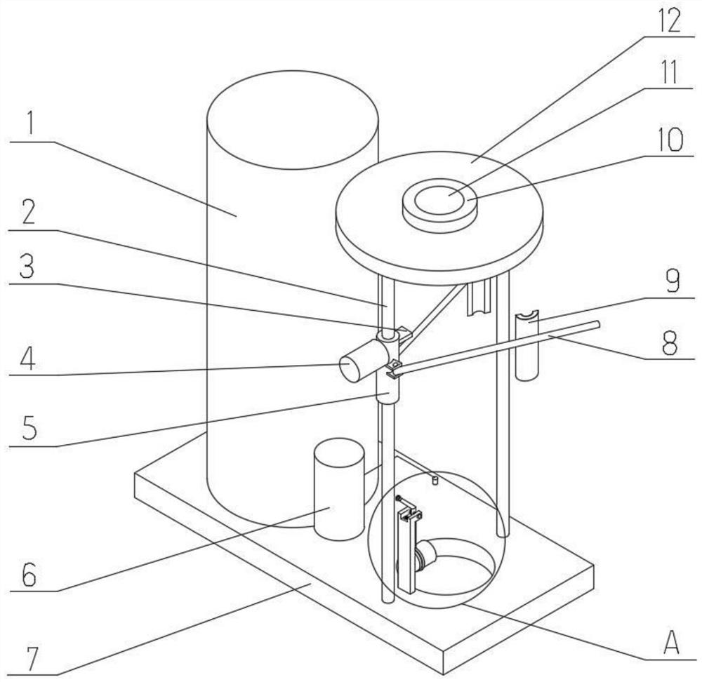
[0027] like figure 1 As shown, a sputum suction tube cleaning device in this embodiment includes a base 7 , a cleaning liquid tank 1 disposed on the left side of the base 7 , and a cleaning rack disposed on the right side of the base 7 . Physiological saline is contained in the cleaning solution tank 1 as a cleaning solution for flushing the inner wall of the sputum suction tube. The cleaning solution tank 1 has a relatively large capacity, and a sufficient amount of physiological saline can be prepared at one time to meet the use of multiple patients without cross-contamination. The cleaning rack is provided with an inner wall cleaning mechanism and an outer wall cleaning mechanism, which wipe and clean the outer wall of the sputum suction tube, and rinse and clean the inner wall of the sputum suction tube by receiving the physiological saline in the cleaning liquid tank 1 . The cleaning rack is also equipped with actuators that slide vertically, and the outer wall cleaning ...


PUM


Abstract

The invention discloses sputum suction tube cleaning equipment. The sputum suction tube cleaning equipment comprises a cleaning liquid tank and a cleaning frame; an outer wall cleaning mechanism is arranged on the upper portion of the cleaning frame, and an inner wall cleaning mechanism is arranged on the lower portion of the cleaning frame; semicircular wiping pieces distributed in pairs are arranged in the outer wall cleaning mechanism, and the wiping pieces distributed in pairs are used for being buckled to the outer wall of a sputum suction tube to form a closed ring shape and slide in the length direction of the sputum suction tube to wipe the outer wall of the sputum suction tube; the inner wall cleaning mechanism is provided with a liquid cup, and the liquid cup is used for moving to the head end of the sputum suction tube and receiving cleaning liquid in the cleaning liquid tank so that the head end of the sputum suction tube can suck the cleaning liquid to wash the inner wall; and an execution piece sliding in the vertical direction is further arranged in the cleaning frame and used for driving the wiping pieces distributed in pairs to be buckled to the outer wall of the sputum suction tube in the sliding process and wiping the sputum suction tube, driving the liquid cup to move to the head end of the sputum suction tube and connecting a cleaning liquid into the sputum suction tube. The sputum suction tube can be effectively cleaned, and meanwhile pollution of residual sputum on the sputum suction tube to personnel or the cleaning liquid is reduced.

Description

technical field [0001] The invention relates to the field of medical equipment, in particular to a sputum suction tube cleaning device. Background technique [0002] Sputum suction refers to a method of sucking out respiratory secretions through the oral cavity, nasal cavity, and artificial airway (tracheotomy) to keep the airway unobstructed and prevent complications such as aspiration pneumonia, atelectasis, and suffocation. It is indicated for comatose patients, patients with a lot of sputum and the possibility of suffocation, and patients who need intratracheal administration, injection of contrast medium or dilution of sputum. Existing sputum suction is usually achieved through a sputum suction tube, which is a slender flexible hose, whose head end is used to insert into the patient's respiratory tract and has a sputum suction port, and its tail end is connected with negative pressure suction equipment , to suck out the phlegm in the respiratory tract with the negative...

Claims


Application Information

Patent Timeline
IPC IPC(8): A61M25/00B08B9/023B08B9/032B08B13/00
CPCA61M25/00B08B9/0321B08B9/023B08B13/00A61M2025/0019
Inventor 张玉林张红梅孙宇昆韩玉荣王艳霞陈书玉田倩倩何乐张磊
Owner 周口市中医院
Why Eureka
Try Eureka