
Combined machining tool and combined machining method for force bearing support plate

A combined processing and tooling technology, applied in metal processing equipment, metal processing mechanical parts, supports, etc., can solve the problem of difficulty in ensuring the circular runout and taper requirements of the outer end face, and achieve the effect of improving processing efficiency and reducing the number of tooling.

Active Publication Date: 2021-12-10
AECC COMML AIRCRAFT ENGINE CO LTD
View PDF13 Cites 0 Cited by
  • Summary
  • Abstract
  • Description
  • Claims
  • Application Information

AI Technical Summary

Problems solved by technology

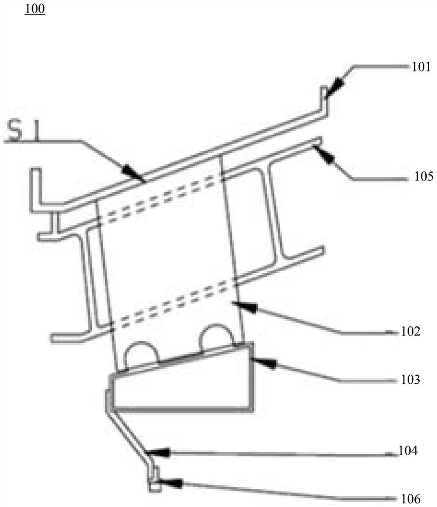
Due to the accumulated machining errors when the bearing support plate 102 and the inner casing 103 are separately processed, it is difficult to ensure the circular runout and taper requirements of the outer end surface after the bearing support plate 102 is installed.

Method used


Image

  • Combined machining tool and combined machining method for force bearing support plate
  • Combined machining tool and combined machining method for force bearing support plate
  • Combined machining tool and combined machining method for force bearing support plate

Examples


Embodiment Construction

[0053] It should be noted that, in the case of no conflict, the embodiments in the present application and the features in the embodiments can be combined with each other.

[0054]The technical solutions in the embodiments of the present application will be clearly and completely described below in conjunction with the drawings in the embodiments of the present application. Apparently, the described embodiments are only some of the embodiments of the present application, rather than all the embodiments. The following description of at least one exemplary embodiment is merely illustrative in nature and in no way serves as any limitation of the application, its application or uses. Based on the embodiments in this application, all other embodiments obtained by persons of ordinary skill in the art without creative efforts fall within the protection scope of this application.

[0055] It should be noted that the terminology used here is only for describing specific implementation...


PUM


Abstract

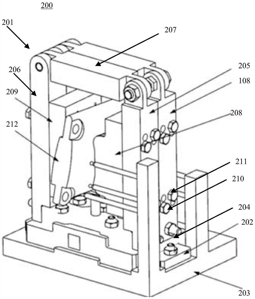
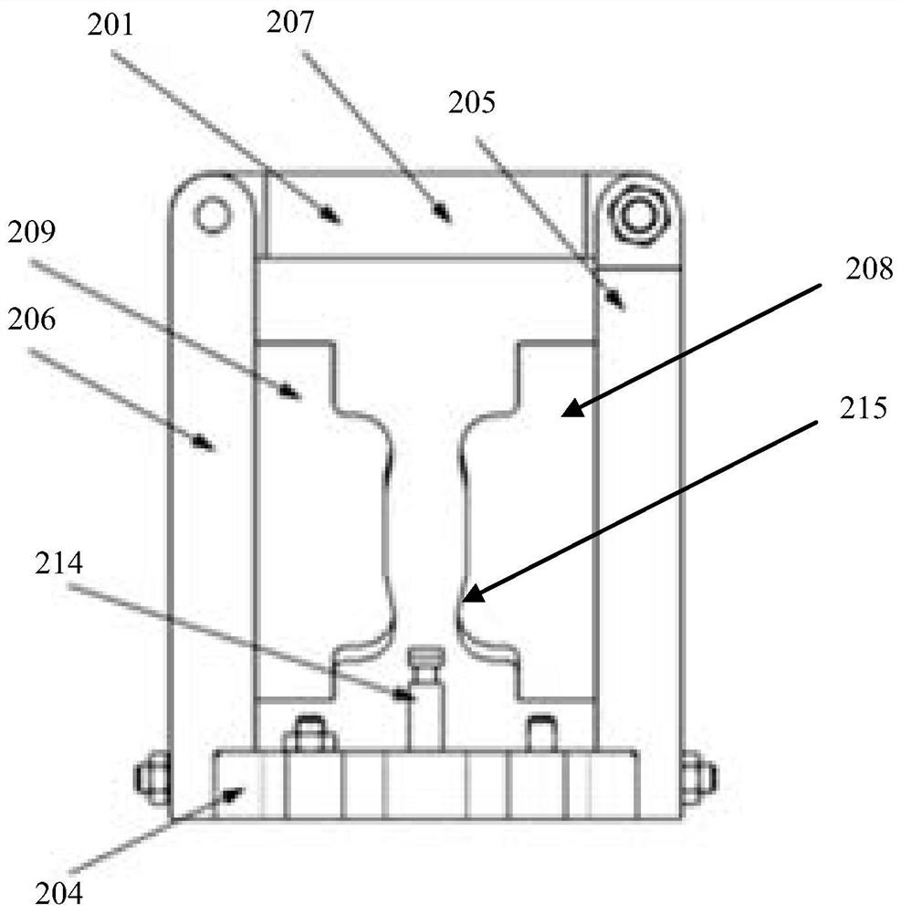
The invention relates to a combined machining tool and a combined machining method for a force bearing support plate. The combined machining tool comprises at least two sets of clamping tools, wherein each set of clamping tool comprises a base, a first stand column, a second stand column, a cross beam, a first shape follow-up clamping block and a second shape follow-up clamping block; the first stand columns and the second stand columns are vertically and oppositely arranged on the bases; the two ends of the cross beams are fixedly arranged at the tops of the first stand columns and the tops of the second stand columns correspondingly; and the first shape follow-up clamping blocks and the second shape follow-up clamping blocks are oppositely arranged on the inner sides of the first stand columns and the inner sides of the second stand columns and used for clamping the two sides of the force bearing supporting plate. According to the combined machining tool and the combined machining method for the force bearing supporting plate provided by the invention, the positioning requirement and the rigidity requirement of the force bearing supporting plate in the machining process can be met, the number of tools is reduced, and the machining efficiency is improved.

Description

technical field [0001] The invention relates to the technical field of aero-engine manufacturing, in particular to a combined processing tool for a bearing support plate and a combined processing method thereof. Background technique [0002] Aeronautical turbofan engine with high bypass ratio (hereinafter referred to as "aero engine") includes fan booster stage, high-pressure compressor, combustion chamber, high-pressure turbine, low-pressure turbine and other components. The box part is used to guide the transition of gas from the outlet of the high-pressure turbine to the inlet of the low-pressure turbine, and install the fixed bearing. figure 1 A schematic structural diagram of an aero-engine interstage casing is shown. As shown in the figure, the interstage casing 100 includes main parts such as an outer casing 101, a bearing support plate 102, an inner casing 103, a bearing seat 104, a rectifying vane 105 in a transition section, and a bearing 106, among which the oute...

Claims


Application Information

Patent Timeline
IPC IPC(8): B23C3/00B23C9/00B23Q3/06
CPCB23C3/00B23C9/00B23Q3/06
Inventor 杨伟俊徐虹艳傅将威杨国宝
Owner AECC COMML AIRCRAFT ENGINE CO LTD
Learn More