
Steam turbine blade-cascade assembling frock

A technology for assembling tooling and steam turbines, applied in auxiliary devices, manufacturing tools, metal processing equipment, etc., can solve the problems of increased cost of steam turbines, low work efficiency, lack of versatility, etc., to save materials, improve work efficiency, and reduce tooling Quantity effect

Active Publication Date: 2009-03-25
DONGFANG TURBINE CO LTD
View PDF0 Cites 10 Cited by
  • Summary
  • Abstract
  • Description
  • Claims
  • Application Information

AI Technical Summary

Problems solved by technology

[0004] The previous tooling was designed and manufactured according to a specific specification of the cascade. The diameters of the inner and outer bands and the taper of the outer band are determined. Each tooling is only suitable for one specification of the cascade, and there is no universal However, a steam turbine has many cascades with different specifications, which requires many sets of tooling. These toolings will be scrapped after one-time use, which wastes a lot of materials and increases the cost of the steam turbine.
At the same time, every time a cascade is installed and welded, a tool has to be replaced, and the work efficiency is low

Method used


Image

  • Steam turbine blade-cascade assembling frock
  • Steam turbine blade-cascade assembling frock
  • Steam turbine blade-cascade assembling frock

Examples


Embodiment Construction

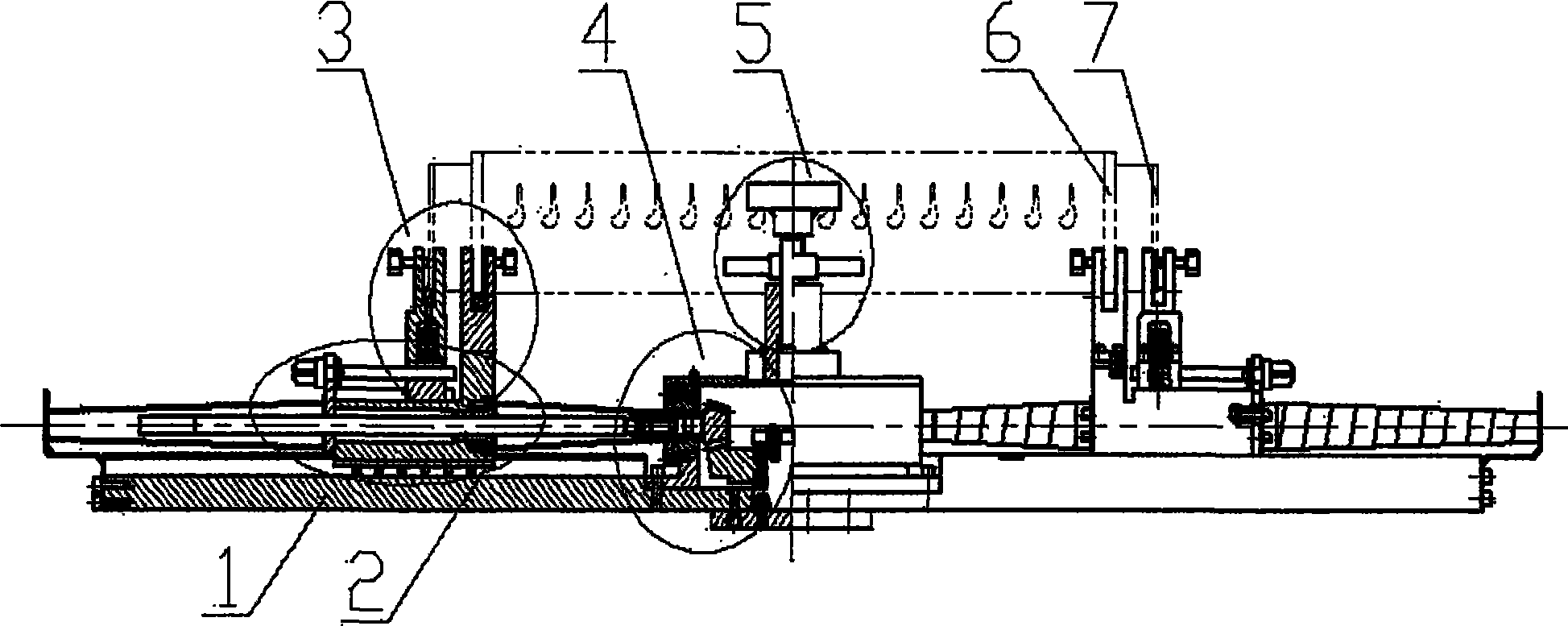
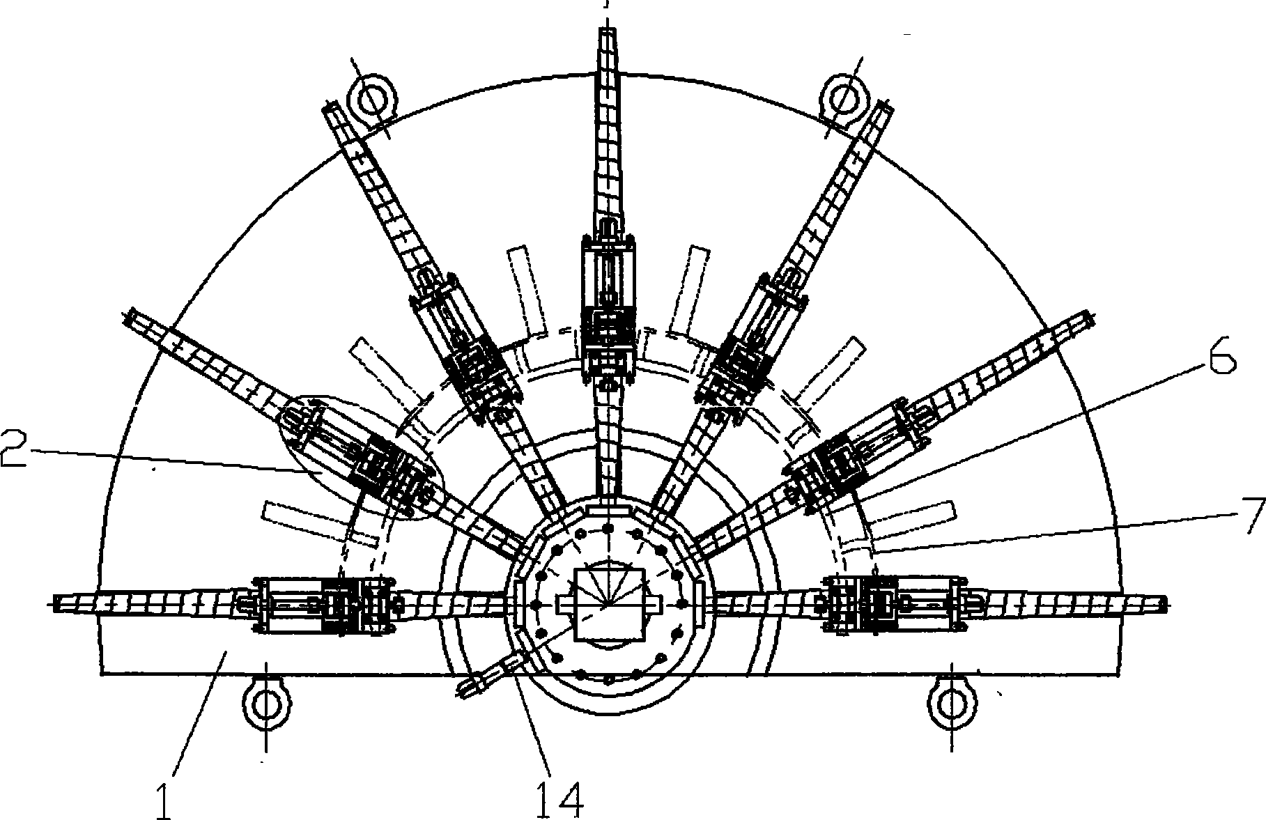
[0022] see figure 1 , figure 2 : This tooling is mainly composed of chassis 1, a plurality of radial sliding devices 2 arranged on the chassis, inner and outer belt clamping mechanisms 3 arranged on the sliding device 2, and arranged in the center of the chassis 1 for driving all sliding devices 2 The synchronously moving transmission mechanism 4 and the cascade arc centering mechanism 5 arranged in the center of the top surface of the transmission mechanism are composed of five parts, and the specific structures of each part are described as follows.

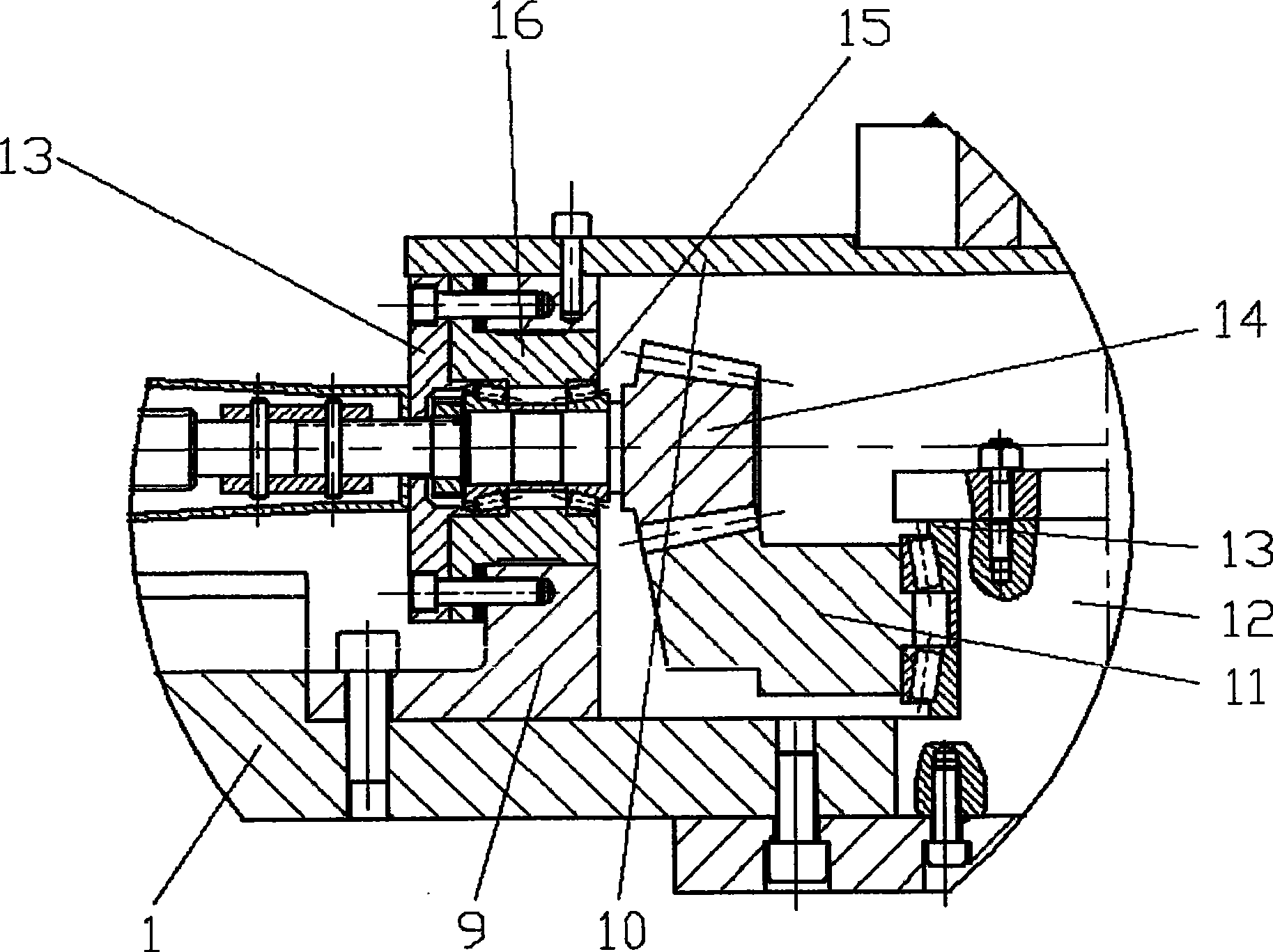
[0023] Chassis 1 is in the shape of a disc with a plurality of trapezoidal chutes 8 on it, seven of which are shown in this example. The chutes are radially distributed with the center of chassis 1 as the origin, and each chute is in On the radius, there is a sliding device 2 radially slidingly matched therein in the chute 8 . The transmission mechanism 4 of the sliding device 2 is arranged in the center of the chassis 1 , s...


PUM


Abstract

The invention discloses a steam turbine cascade assembly fixture which comprises a chassis and a plurality of inner shroud claws and outer shroud claws arranged on the chassis. All the inner shroud claws are arranged on the same circular arc line, the radius of which corresponds to that of the inner shroud. All the outer shroud claws are also arranged on the same circular arc line, the radius of which corresponds to that of the outer shroud. The chassis is provided with radial sliding-groove sliding-seat pairs with the same number as the claws, taking a actinoid shape. The inner shroud claws are arranged on the sliding seat which is provided with a lead screw nut transmission pair. The top of the sliding seat is provided with a radial sliding-groove sliding-block pair, and the sliding block is provide with a lead screw nut transmission pair. The outer shroud claws are fixed on the top of the sliding block. The center of the chassis is provided with a transmission mechanism which enables each sliding seat move synchronously along the respective sliding groove. All the lead screw nut transmission pairs are respectively connected with the transmission mechanism. When in operation, the diameter of the inner shroud and outer shroud and the tapering degree of the outer shroud can be discretionarily adjusted, thereby making the welding assembly and processing be suitable for various types of turbine cascade.

Description

technical field [0001] The invention relates to a steam turbine blade cascade, in particular to a tool used for assembling and welding the blade cascade. Background technique [0002] The steam turbine has multiple working stages, and there are partitions between adjacent working stages. The core part of the partition is the cascade, and the cascade is the interstage channel for steam to enter the next stage from the upper stage. [0003] The cascade is composed of inner and outer belts and guide vanes. During processing, the positioning holes of the guide vanes are cut out on the shroud first. The contour of the positioning holes on the outer belt is consistent with the profile of the top section of the guide vanes. The contour shape of the positioning hole on the guide vane is consistent with the cross-sectional profile of the root end of the guide vane, and then the two ends of the guide vane are respectively embedded in the positioning holes on the inner and outer belts ...

Claims


Application Information

Patent Timeline
IPC IPC(8): B23K37/053
Inventor 李蓉胡剑华唐凯何在勋袁秀坤
Owner DONGFANG TURBINE CO LTD
Learn More