Pipe pile variable-diameter hole guiding and pile pressing synchronous construction equipment and method thereof

A technology of simultaneous construction and variable diameter, applied in drilling equipment and methods, drilling equipment, sheet pile walls, etc., can solve problems such as easy to produce collapsed holes or inclined holes, holes and under-leaded pile ends, and inability to press in. To achieve the effect of controllable soil extrusion effect, high construction efficiency and reliable bearing capacity

Active Publication Date: 2021-12-10
SHANDONG JIANZHU UNIV
View PDF13 Cites 1 Cited by
  • Summary
  • Abstract
  • Description
  • Claims
  • Application Information

AI Technical Summary

Problems solved by technology

Although it can solve the problem of the pipe pile passing through the deep clay layer and the hard soil layer in the middle, this method has many technological processes, high technical requirements for process connection, and high labor, mechanical, and time costs; the two mechanical secondary

Method used


Image

  • Pipe pile variable-diameter hole guiding and pile pressing synchronous construction equipment and method thereof
  • Pipe pile variable-diameter hole guiding and pile pressing synchronous construction equipment and method thereof
  • Pipe pile variable-diameter hole guiding and pile pressing synchronous construction equipment and method thereof

Examples


Embodiment Construction

[0032] The following will clearly and completely describe the technical solutions in the embodiments of the present invention with reference to the accompanying drawings in the embodiments of the present invention. Obviously, the described embodiments are only some, not all, embodiments of the present invention. Based on the embodiments of the present invention, all other embodiments obtained by persons of ordinary skill in the art without creative efforts fall within the protection scope of the present invention.

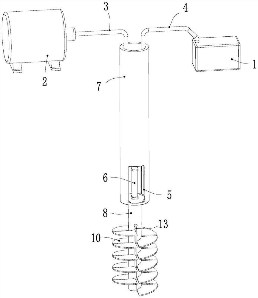
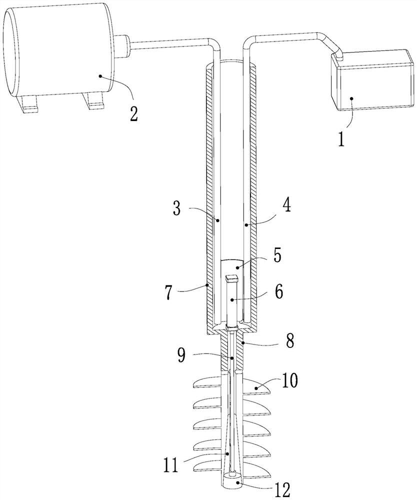
[0033] see Figure 1-2 , the present invention provides a technical solution: a pipe pile variable diameter guide hole and pile pressure synchronous construction equipment, including a drill pipe 7 driven and rotated by an external power device, the lower end of the drill pipe 7 is coaxially fixed with a mounting rod 8, installed The lower end of the rod 8 is provided with a helical blade 10, and the helical blade 10 is driven by the drive unit to expand and contra...


PUM


Abstract

The invention discloses pipe pile variable-diameter hole guiding and pile pressing synchronous construction equipment in the technical field of building construction. The pipe pile variable-diameter hole guiding and pile pressing synchronous construction equipment comprises a drill rod driven by an external power device to rotate, wherein the lower end of the drill rod is coaxially and fixedly connected with a mounting rod; the lower end of the mounting rod is provided with a spiral blade; the spiral blade is driven by a driving unit to radially stretch out and draw back along the mounting rod, so that the adjustment of the hole diameter of a drilling hole is realized; a through groove communicated with the interior of the drill rod is formed in the outer wall of the lower end of the drill rod; a water filling unit and a slurry discharging unit are arranged in the drill rod; the water filling unit is used for filling water into the drill hole; and the slurry discharging unit is used for discharging slurry in the drill hole. The pipe pile variable-diameter hole guiding and pile pressing synchronous construction equipment and method thereof provided by the invention have the beneficial effects that hole guiding and pile pressing can be synchronously carried out, the soil squeezing effect of the pipe pile is controllable, the characteristics of reliable bearing capacity after pile forming and the like are achieved, static pressure of soft soil layers, hard soil layers and soft and hard interbedding areas or construction of variable-diameter hole guiding needed by hammering the pipe pile can be completed, and compared with a traditional construction method, the method has the characteristics that the construction efficiency is high, the soil squeezing effect of the pipe pile is controllable, and the bearing capacity is reliable after pile forming.

Description

technical field [0001] The invention relates to the field of building construction, in particular to a device and method for synchronous construction of pilot holes with variable diameters and pressure piles for pipe piles. Background technique [0002] The pipe pile is a hollow body slender concrete prefabricated component made by pretensioning prestressing process and centrifugal forming method. In 1987, the Third Navigation Engineering Bureau of the Ministry of Communications of my country introduced a complete set of prestressed high-strength concrete pipe pile production lines from Japan. In the late 1980s, China Ningbo Zhedong Cement Products Co., Ltd., with the cooperation of relevant scientific research institutes, developed the pretensioning prestressing method through the transformation of pipe piles in view of the characteristics of more silt and soft soil layers in my country's coastal areas. Concrete thin-walled pipe piles. Pipe piles are widely used in enginee...

Claims


Application Information

Patent Timeline
IPC IPC(8): E02D7/26E02D7/30E21B3/00E21B7/28E21B21/00
CPCE02D7/26E02D7/30E21B3/00E21B7/28E21B21/00E02D2250/0038
Inventor 尚文涛魏焕卫王培森王新泉谭立雪李彦
Owner SHANDONG JIANZHU UNIV
Why Eureka
Try Eureka