Construction method and application of spine mark point positioning model

A construction method and a technology of marking points, which are applied in the field of medical image processing, can solve problems such as the inability to accurately locate spinal marking points, and achieve the effect of improving accuracy and stability, improving accuracy, and high accuracy

Pending Publication Date: 2021-12-10
HUAZHONG UNIV OF SCI & TECH
View PDF0 Cites 0 Cited by
  • Summary
  • Abstract
  • Description
  • Claims
  • Application Information

AI Technical Summary

Problems solved by technology

[0005] In view of the above defects or improvement needs of the prior art, the present invention provides a construction method and application of a spine marker point positioning model to solve the technical problem that the prior art cannot accurately locate the spine marker points

Method used


Image

  • Construction method and application of spine mark point positioning model
  • Construction method and application of spine mark point positioning model
  • Construction method and application of spine mark point positioning model

Examples


Embodiment 1

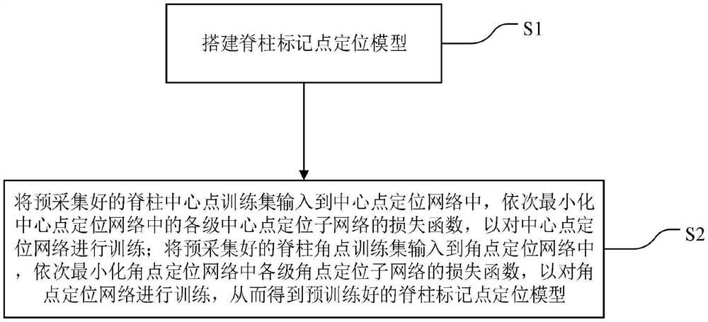
[0058] A method for constructing a spinal marker point positioning model, such as figure 1 shown, including the following steps:

[0059] S1. Build a spine marker point positioning model;

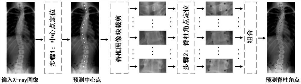
[0060] Specifically, such as figure 2 As shown, the spine marker location model includes a center point location network, a segmentation module, a corner point location network and a combination module; the center point location network includes multiple cascaded center point location sub-networks; the corner point location network includes multiple cascaded The corner location sub-network of the center point location sub-network and the corner point location sub-network are both CNN-based networks.

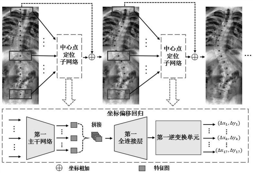
[0061] Central point positioning network:

[0062] The central point positioning network is used to perform multi-level regression on the coordinate offset of each spine center point in the spine image after PCA transformation based on the cascaded center point positioning sub-network, so ...

Embodiment 2

[0105] A method for locating spinal markers, comprising:

[0106] Input the spinal column image to be positioned into the spine marker point positioning model obtained by adopting the construction method of the spinal marker point positioning model described in Embodiment 1, and obtain the coordinates of each corner point on the spine image.

[0107] The relevant technical features are the same as those in Embodiment 1, and will not be repeated here.

[0108] Further, as Figure 4 Shown is the result map of spine center point positioning obtained by the center point positioning network with successively increasing levels in the center point positioning network; Figure 5 Shown is the results of spine corner positioning obtained by the corner positioning subnetwork with increasing series in the corner positioning network; where the black circle represents the position of the predicted point, and the number represents the mean square error between the predicted point coordinate...

Embodiment 3

[0114] A spinal marker point positioning system, comprising:

[0115] A model construction module, configured to execute the method for constructing the spinal marker point positioning model provided in Embodiment 1 of the present invention, to obtain the spinal column marker point positioning model;

[0116] The positioning module is configured to input the spine image to be positioned into the spine marker point positioning model to obtain the coordinates of each corner point on the spine image.

[0117] The relevant technical features are the same as those in Embodiment 1, and will not be repeated here.


PUM


Abstract

The invention discloses a construction method and application of a spine mark point positioning model, and belongs to the field of medical image processing. The constructed spine mark point positioning model comprises a central point positioning network, a segmentation module, a corner positioning network and a combination module; the central point positioning network comprises a plurality of cascaded central point positioning sub-networks; the corner positioning network comprises a plurality of cascaded corner positioning sub-networks; according to the invention, multi-stage coordinate offset regression is carried out based on the cascaded sub-networks in a spine central point positioning stage and a spine corner positioning stage, and PCA mark point shape constraints are introduced, so that each cascaded sub-network is regressed to the position offset after PCA dimension reduction instead of directly regressing the coordinate points, the problem that mark points attract each other due to inter-spine homogenization in a regression process is solved, and the accuracy of spine mark point positioning is greatly improved.

Description

technical field [0001] The invention belongs to the field of medical image processing, and more specifically relates to a construction method and application of a spinal marker point positioning model. Background technique [0002] In the computer-aided diagnosis of spinal diseases, the location of spinal markers is a very critical step, and it is usually applied to tasks such as Cobb angle calculation, biomechanical load analysis, and vertebral fracture detection. However, manually identifying 17 vertebrae and locating the 4 corner points on each vertebra is very time-consuming, so people are interested in using a computer to automatically locate 68 points on the spine (17 segments of vertebrae, 4 corner points on each vertebra). ) are in high demand. Although the task of automatically locating spinal markers has been studied for decades, due to the blurring of the X-ray image itself, the overlapping of soft tissues, and the high texture similarity of adjacent vertebral bo...

Claims


Application Information

Patent Timeline
Patent Type & Authority Applications(China)
IPC IPC(8): G06T7/73G06T7/11G06K9/62G06K9/46G06N3/04G06N3/08
CPCG06T7/73G06T7/11G06N3/08G06T2207/20132G06T2207/20164G06T2207/30012G06T2207/30204G06T2207/20081G06N3/045G06F18/2134
Inventor 王植炜李强吕进鑫杨云桥
Owner HUAZHONG UNIV OF SCI & TECH
Why Eureka
Try Eureka