
A Diode Pumped Gas Laser System Based on Electromagnetic Driving Mode

An electromagnetic drive and gas laser technology, applied in the laser field, can solve the problems of low thermal conductivity, single-channel output power of all solid-state lasers, finite mode volume, etc., and achieve high electro-optical efficiency, good heat dissipation effect, and low working fluid consumption small effect

Active Publication Date: 2022-03-01
NAT UNIV OF DEFENSE TECH
View PDF7 Cites 0 Cited by
  • Summary
  • Abstract
  • Description
  • Claims
  • Application Information

AI Technical Summary

Problems solved by technology

However, the single-channel output power of all-solid-state lasers has always remained at the 10,000-watt level, and the power level of 100,000 watts requires multiple beams. As for the megawatt-level solid-state laser system, there is currently no clear technical route
The root cause still comes back to the problem of heat dissipation. Since the solid-state laser medium can only dissipate heat through conduction, and its thermal conductivity is relatively low, it can only be made into structures with large specific surface areas such as thin sheets and optical fibers, which correspondingly lead to limited mode volume and other technical obstacles

Method used


Image

  • A Diode Pumped Gas Laser System Based on Electromagnetic Driving Mode
  • A Diode Pumped Gas Laser System Based on Electromagnetic Driving Mode
  • A Diode Pumped Gas Laser System Based on Electromagnetic Driving Mode

Examples


Embodiment 1

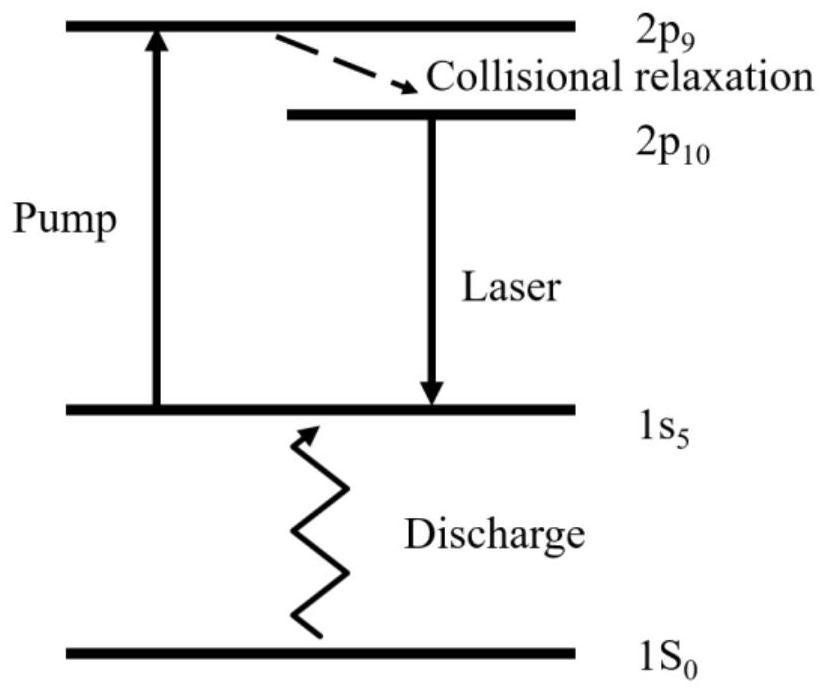
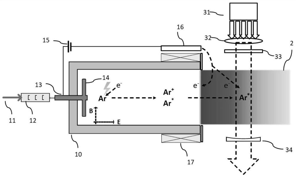
[0031] Embodiment 1: When the laser working medium generating device 1 based on the electromagnetic drive mode is a metastable inert gas atom generating device based on the Hall thruster working mode, the structure of the laser system is as follows image 3 shown. image 3 Among them, the laser working medium generating device 1 is a metastable inert gas atomic generating device based on the Hall thruster working mode, including a gas supply pipeline 11, and the gas flowing in the pipeline is a high-purity argon and helium mixed gas source, Among them, argon is the laser working medium, accounting for 5% by mole, and helium is the buffer gas, accounting for 95% by mole, which is used to promote 2p 9 →2p 10 No radiative transition and atomic absorption line broadening, in order to prevent the impurity gas for 1s 5 Collision quenching of metastable argon atoms, the impurity content of the gas source is controlled within 1ppm, the pneumatic control element 12 includes a mass fl...

Embodiment 2

[0033] Embodiment 2: When the laser working medium generating device 1 based on the electromagnetic drive mode is a nano-gas generating device based on the pulsed plasma propulsion mode, the structure of the laser system is as follows Figure 5 Shown:

[0034] Figure 5 Among them, the laser working medium generating device 1 is a pulsed plasma thruster, including an energy storage capacitor 11, which stores external electric energy and serves as a system discharge source; parallel plate electrodes 12 and 13 are used as an anode and a cathode, respectively; a ground terminal 14, Connected to the cathode 13, the rare earth element target 15, taking ytterbium as an example, has a purity ≥ 99.9%, and is used as a working fluid material for ionization; the spring 16 is used to maintain the front end of the target at a constant level after the target is bombarded by electrons and the mass is reduced. Position, for the system to continuously provide rare earth ion implantation, gas...


PUM


Abstract

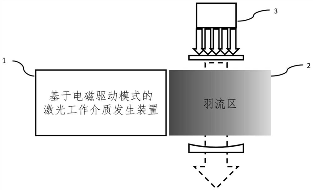
The invention belongs to the field of laser technology, and specifically relates to a semiconductor pumped gas laser system based on an electromagnetic drive mode, including a laser working medium generating device based on an electromagnetic drive mode, a plume area, and a semiconductor pump system; when the system is working, the laser The working medium generating device ionizes the working medium under the action of electric field and magnetic field to generate plasma, and the plasma is accelerated under the combined action of electromagnetic field to form a plume area, which can be used as the working medium of the laser gain medium in the semiconductor The laser output is realized under the pumping action of the pumping system; at the same time, due to the high-speed movement of the working medium in the plume area, the waste heat generated during the laser pumping process is efficiently discharged; it has all-electric operation, light weight and compactness, high specific power, and high efficiency The advantages of thermal control and single-aperture output promote the development of a new generation of laser light sources with high electro-optical efficiency, high beam quality and high average power.

Description

technical field [0001] The invention belongs to the technical field of lasers, and in particular relates to a semiconductor pumped gas laser system based on an electromagnetic drive mode. Background technique [0002] Since the advent of lasers in the 1960s, people have been devoting themselves to the development of laser systems with high average power, high conversion efficiency and high beam quality, which have important applications in fields such as industry and national defense. The essence of the laser system is to convert the pump energy (such as chemical energy, electrical energy, light energy, etc.) into a laser output with high coherence and low entropy. It leads to the deterioration and damage of laser system performance, and is more obvious in high-energy laser systems. The key to the development of high-energy laser systems lies in thermal management. [0003] As the only light source that achieves megawatt-level output at present, the chemical laser is not on...

Claims


Application Information

Patent Timeline
Patent Type & Authority Patents(China)
IPC IPC(8): H01S3/032H01S3/036H01S3/0933
CPCH01S3/0326H01S3/0933H01S3/036
Inventor 许晓军杨子宁王蕊王红岩韩凯杨旭
Owner NAT UNIV OF DEFENSE TECH
Learn More