Blade circumferential arc hammer foot type tenon machining device and machining method thereof

A processing device and blade technology, which is applied to metal processing equipment, manufacturing tools, details of milling machine equipment, etc., can solve the problems of large deformation of the knife, high precision requirements for the height deviation of the two shoulders, and low processing efficiency, so as to meet the processing efficiency. and dimensional accuracy, solving poor surface quality, and improving the quality of finished products

Pending Publication Date: 2021-12-14
AECC AERO SCI & TECH CO LTD
View PDF14 Cites 0 Cited by
  • Summary
  • Abstract
  • Description
  • Claims
  • Application Information

AI Technical Summary

Problems solved by technology

In order to alleviate the stress concentration, the tenon is transferred to a complex curved surface 4 composed of a small arc 4-1, a small straight line 4-2, and a large arc 4-3 around the engine axis; in order to strictly control the shape and position error of the tenon, The design basis and size of the tenon are complex and upgraded. The symmetrical mid-section plane 6 of the radial plane of the back of the basin, the reference points 7 and 8 on both sides of the two shoulder arcs, and the symmetrical mid-section plane 9 of the inlet and exhaust side end faces are the first and second. , three benchmarks (such as figure 2 shown), the size of the tenon is the surface profile dimension of the associated reference position; the processing difficulties of the circumferential arc hammer foot type tenon of the blade are: (1) the surface quality and flatness of the large-sized plane of the tenon horizontal plus integrated milling are poor, and the large-diameter The processing efficiency of the transfer arc surface is low, the surface quality and dimensional accuracy are difficult to guarantee, and the accuracy of the arc height deviation of the two shoulders is high.
[0003] For large-size planes, high-speed steel helical tooth cylindrical milling cutters are commonly used for milling. The long overhang tool has poor rigidity, which makes the tool deformed greatly, the tool is easy to wear, and the straightness accuracy of the cutting edge loses quickly, resulting in poor surface quality and large surface inclination. ;
[0004] For large-diameter complex transition surfaces, small-diameter ball-end milling cutters are used for layered milling, which has low processing efficiency, difficulty in meeting the requirements for surface quality and dimensional accuracy, and is difficult to grind due to the size of the tool; disc-shaped milling cutters cannot be used in the affected areas. Used in tenon and groove spaces with limited space, resulting in difficult processing and low efficiency

Method used


Image

  • Blade circumferential arc hammer foot type tenon machining device and machining method thereof
  • Blade circumferential arc hammer foot type tenon machining device and machining method thereof
  • Blade circumferential arc hammer foot type tenon machining device and machining method thereof

Examples


Embodiment 1

[0046] The present invention also provides a method for processing blade circumferential arc hammer foot type tenons, which includes the following steps:

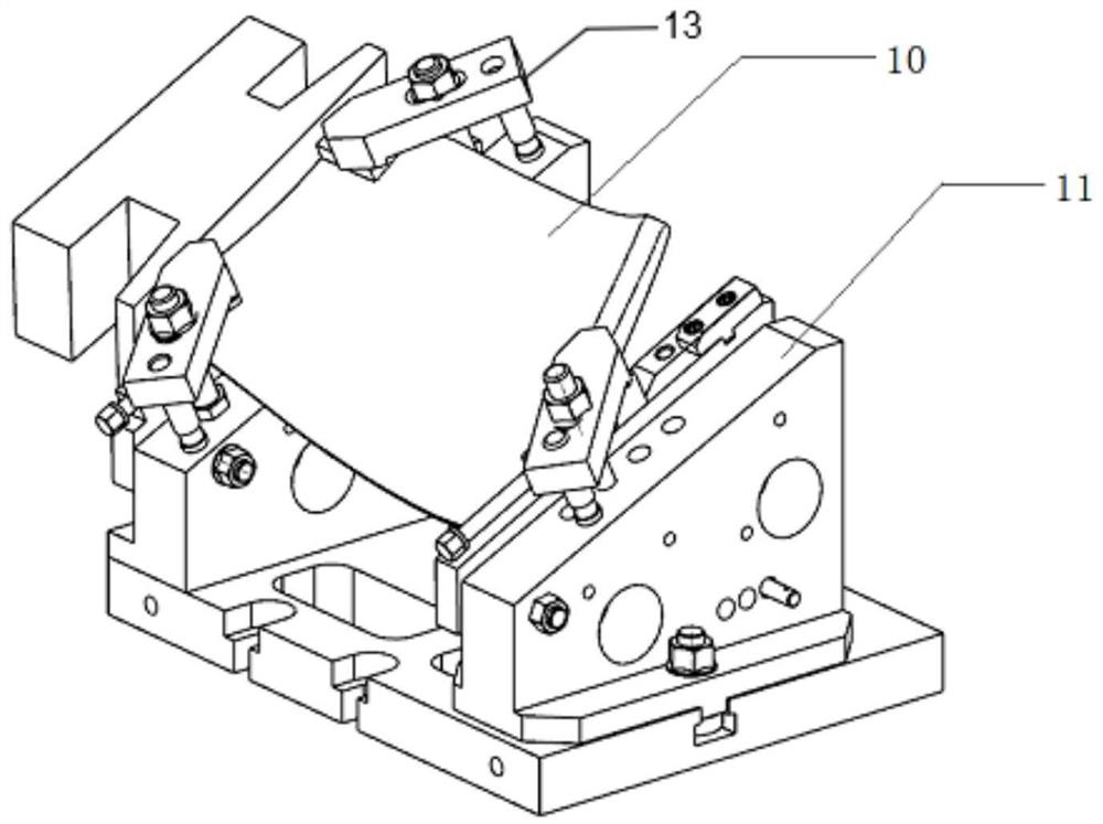
[0047] S1: Clamp the blade blank 10 with the blade body and blade tip process platform through the first positioning seat 11-3 and the second positioning seat 11-4. After clamping, the front and rear end faces of the tenon are parallel to the plumb direction, and the back of the basin is inclined. On the horizontal plane; the inclination angle of the first positioning seat 11-3 and the second positioning seat 11-4 is 23°;

[0048] S2: Use a round blade universal milling cutter for rough machining, scan and mill the bottom surface and surroundings of the tenon, leaving a margin of 0.5-0.7mm;

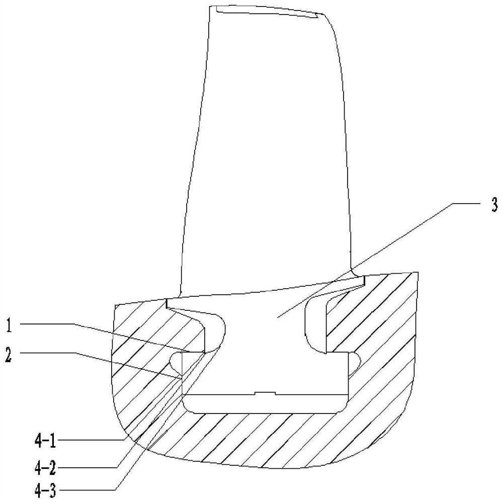
[0049] S3: Use a helical toothed cylindrical milling cutter to mill the radial plane 3 on the back of the mortise basin. During milling, the tool passes along the oblique line to process the side surface. The machine speed is 200-300r / ...

Embodiment 2

[0054] The present invention also provides a method for processing blade circumferential arc hammer foot type tenons, which includes the following steps:

[0055] S1: Clamp the blade blank 10 with the blade body and blade tip process platform through the first positioning seat 11-3 and the second positioning seat 11-4. After clamping, the front and rear end faces of the tenon are parallel to the plumb direction, and the back of the basin is inclined. On the horizontal plane; the inclination angle of the first positioning seat 11-3 and the second positioning seat 11-4 is 25°;

[0056] S2: Use a round blade universal milling cutter for rough machining, scan and mill the bottom surface and surroundings of the tenon, leaving a margin of 0.5-0.7mm;

[0057] S3: Use a helical toothed cylindrical milling cutter to mill the radial plane 3 on the back of the mortise basin. During milling, the tool passes along the oblique line to process the side surface. The machine speed is 200-300r / ...


PUM


Abstract

The invention discloses a blade circumferential arc hammer foot type tenon machining device and a machining method thereof. The blade circumferential arc hammer foot type tenon machining device comprises a clamping assembly used for clamping a blade to be machined and a cutter assembly used for machining the blade to be machined, wherein the cutter assembly comprises a spiral tooth cylindrical milling cutter used for tenon basin back radial plane machining and a ball-end milling cutter used for machining a blade air inlet and exhaust edge switching curved surface. The clamping assembly can adapt to the blades of different sizes, the clamping flexibility is effectively improved, damage to the outer walls of the blades is avoided, and the problems that the large plane machining size of the blades is unstable and the surface quality is poor are effectively solved through the spiral tooth cylindrical milling cutter; and meanwhile, the machining efficiency and the size precision of a switching arc curved surface are greatly met through the forming milling of the ball-end milling cutter, horizontal machining integrated milling of the circumferential arc hammer foot type tenon is achieved, the requirements for the size precision, the surface quality and the machining efficiency of the tenon are met, and the quality of a finished blade product is improved.

Description

technical field [0001] The invention relates to the technical field of blade tenon processing, in particular to a blade circumferential arc hammer foot type tenon processing device and a processing method thereof. Background technique [0002] like figure 1 As shown, the gas turbine compressor circumferential arc hammer-foot tenon blade is installed in the rotor wheel groove along the circumference through the root of the hammer foot, and the radial and The axial limit surface is installed in contact. Due to the wide chord design of the blade shape and the extension of the radial depth of the wheel groove, the axial and radial dimensions of the tenon are increased, forming a large-sized basin back radial plane 3 . In order to alleviate the stress concentration, the tenon is transferred to a complex curved surface 4 composed of a small arc 4-1, a small straight line 4-2, and a large arc 4-3 around the engine axis; in order to strictly control the shape and position error of...

Claims


Application Information

Patent Timeline
Patent Type & Authority Applications(China)
IPC IPC(8): B23C3/18
CPCB23C3/18
Inventor 蒲双龙陈勇邓杰陈蕊朱才彬蔡典祥周勇易杰
Owner AECC AERO SCI & TECH CO LTD
Why Eureka
Try Eureka