Light prefabricated stair and manufacturing method thereof

A manufacturing method and lightweight technology, applied to chemical instruments and methods, stairs, manufacturing tools, etc., can solve the problems of high labor intensity, low efficiency, uneven stress on the steel cage, etc., to increase connectivity and integrity, Effect of improving impact strength and improving load transmission efficiency

Active Publication Date: 2021-12-14
台州普立德建筑科技有限公司
View PDF8 Cites 0 Cited by
  • Summary
  • Abstract
  • Description
  • Claims
  • Application Information

AI Technical Summary

Problems solved by technology

[0004] During the processing of the steel cage, the labor intensity of the workers is high and the efficiency is low, and the binding can only be done manually. The spacing of the steel bars of the steel cage is difficult to control. Excessive spacing deviation will cause uneven force on the steel cage and affect the prefabricated stairs. product quality
[0005] In addition, in order to pursue the lightness of the stairs, most of them set weight-reducing holes in the treads, or use foamed cement to make the treads. These methods all have a certain impact on the compressive strength, bending strength and impact strength of the stairs, which is not conducive to The long-term use of stairs is also not conducive to the safety of the building

Method used


Image

  • Light prefabricated stair and manufacturing method thereof
  • Light prefabricated stair and manufacturing method thereof
  • Light prefabricated stair and manufacturing method thereof

Examples


Embodiment 1

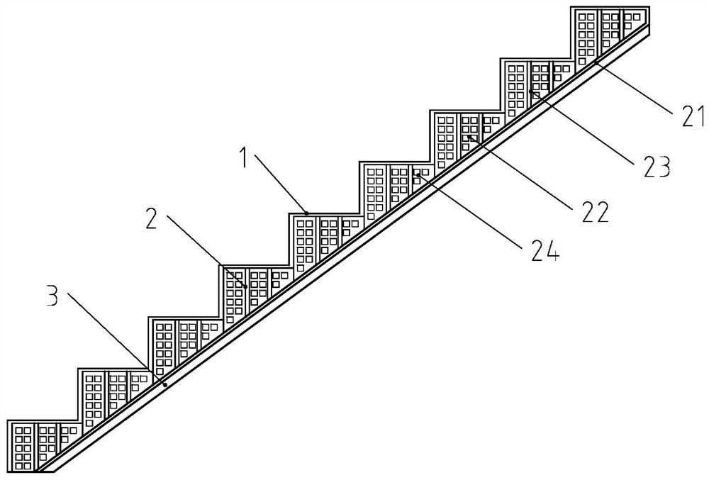
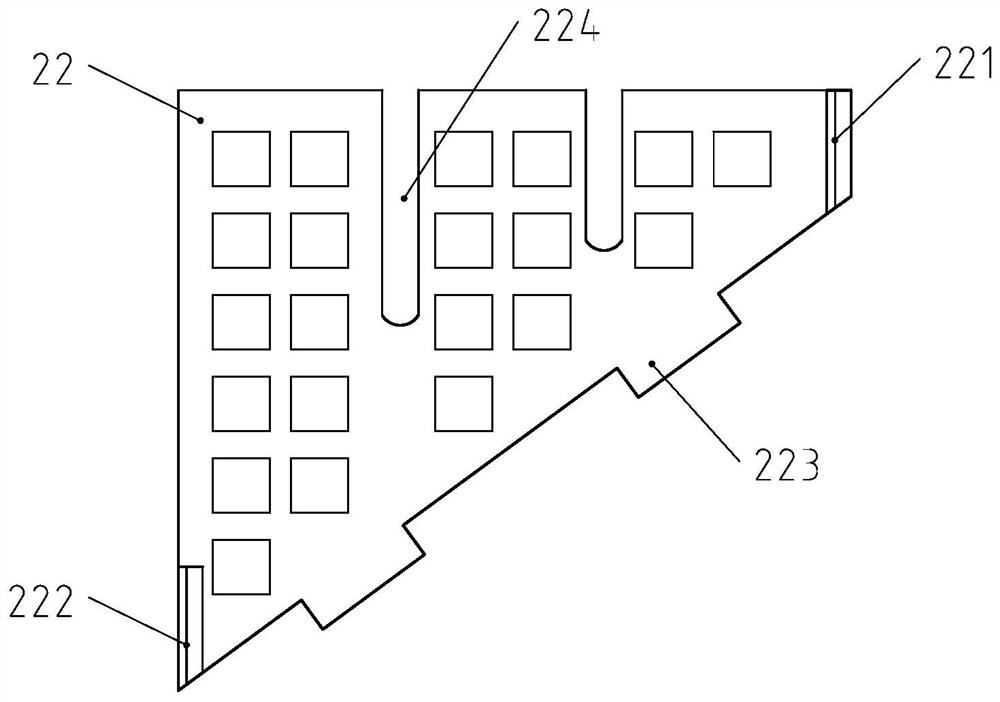
[0039] Such as figure 1 The shown lightweight prefabricated staircase includes a concrete staircase main body 1 and a plate-type composite skeleton 2 arranged in the concrete staircase main body. The main body of the concrete staircase 1 is formed by pouring foamed concrete 3. The panel composite skeleton 2 includes a bottom plate 21, several support plates 22 and several connecting plates 23. Several support plates 22 are continuously arranged on the surface of the bottom plate 21 along the length direction of the bottom plate 21. Several support plates 22 are arranged on the surface of the bottom plate 21 at intervals along the width direction of the bottom plate 21, and several connecting plates 23 are arranged at intervals along the length direction of the bottom plate 21 and intersect with several support plates 22. The unit hole 24 of the cloth.

[0040]Through the above technical solution, the plate-type combined skeleton 2 composed of the support plate 22, the connect...

Embodiment 2

[0042] Such as figure 1 The shown lightweight prefabricated staircase includes a concrete staircase main body 1 and a plate-type composite skeleton 2 arranged in the concrete staircase main body.

[0043] The main body of the concrete staircase 1 is formed by pouring foamed concrete 3. The panel composite skeleton 2 includes a bottom plate 21, several support plates 22 and several connecting plates 23. Several support plates 22 are continuously arranged on the surface of the bottom plate 21 along the length direction of the bottom plate 21. Several support plates 22 are arranged on the surface of the bottom plate 21 at intervals along the width direction of the bottom plate 21 , and several connecting plates 23 are arranged at intervals along the length direction of the bottom plate 21 and intersect with several support plates 22 .

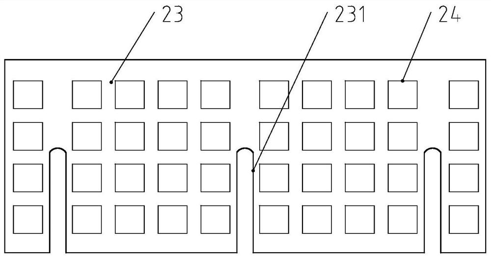
[0044] The surface of each supporting plate 22 and the surface of each connecting plate 23 are provided with several uniformly distributed unit h...

Embodiment 3

[0058] A lightweight prefabricated staircase, the technical solution is the same as that of Embodiment 2, the difference is that:

[0059] Such as Figure 5 As shown, the unit hole 24 includes an upper unit hole 241 and a lower unit hole 242. The upper unit hole 241 is located on the surface of the support plate 22 away from the position of the bottom plate 21 and the surface of the connecting plate 23 is away from the position of the bottom plate 21. The lower unit hole 242 is located on the support plate 22. The surface of the plate 22 is close to the bottom plate 21 and the surface of the connecting plate 23 is close to the bottom plate 21. The aperture of the upper unit hole 241 is the same as the aperture of the lower unit hole 242, and the distance between the upper unit holes 241 is smaller than that between the lower unit holes 242. spacing.

[0060] Foamed concrete 3 includes the following components by weight: 420 parts of lightweight aggregate, 350 parts of cement,...


PUM


Abstract

The invention provides a light prefabricated stair which is light in weight and good in strength. The light prefabricated stair comprises a concrete stair body and a plate-type combined framework arranged in the concrete stair body; the concrete stair body is formed by pouring foamed concrete; the plate-type combined framework comprises a bottom plate, a plurality of supporting plates and a plurality of connecting plates; the multiple supporting plates are continuously arranged on the surface of the bottom plate in the length direction of the bottom plate; the multiple supporting plates are arranged on the surface of the bottom plate at intervals in the width direction of the bottom plate; the multiple connecting plates are arranged at intervals in the length direction of the bottom plate and intersect with the multiple supporting plates; and a plurality of evenly-distributed unit holes are formed in the surface of each supporting plate and the surface of each connecting plate. According to the light prefabricated stair, each step plate part on the concrete stair body is effectively supported through the plate-type combined framework, so that the situation that the compressive strength, the bending strength and the impact strength are reduced due to the fact that no framework support exists in step plates poured only by foamed concrete is avoided.

Description

technical field [0001] The invention relates to a staircase and a manufacturing method thereof, in particular to a lightweight prefabricated staircase and a manufacturing method thereof. Background technique [0002] Prefabricated stairs are an important type of prefabricated components in prefabricated concrete structures, mainly divided into prefabricated beam stairs and prefabricated slab stairs. The prefabricated beam staircase is composed of stringers and treads, the treads are supported on the stringers, and the stringers are supported on the platform beams at both ends of the stairs. The platform beams and stringers are cast in situ and the treads are fully prefabricated. The prefabricated slab staircase is to prefabricate the inclined beams and the treads as a whole, and they are directly lapped on the platform beams during construction. The reinforcement of the slab stairs is relatively simple. Usually, a layer of reinforcement cage is laid under the treads, and th...

Claims


Application Information

Patent Timeline
Patent Type & Authority Applications(China)
IPC IPC(8): E04F11/02E04F11/022E04F11/09C04B28/06C04B20/02C04B38/10C04B18/02B28C5/40B28C5/38B28B23/02
CPCE04F11/02E04F11/022E04F11/09C04B28/06C04B20/023C04B18/027C04B38/10B28C5/402B28C5/388B28B23/02C04B2201/50E04F2011/0212C04B7/02C04B18/08C04B18/12C04B14/06C04B18/248C04B24/14C04B18/023Y02W30/91
Inventor 许可金崇正董荣贵毛应豪金剑雨徐伟力
Owner 台州普立德建筑科技有限公司
Why Eureka
Try Eureka