
Connector and male head and female head thereof, unmanned aerial vehicle, battery, and charger

A technology of connectors and male heads, which is applied in the field of connectors, can solve the problems of large size increase and unfavorable connector miniaturization design, and achieve the effect of increasing the number and facilitating miniaturization design

Pending Publication Date: 2021-12-14
SZ DJI TECH CO LTD
View PDF5 Cites 0 Cited by
  • Summary
  • Abstract
  • Description
  • Claims
  • Application Information

AI Technical Summary

Problems solved by technology

However, this method increases the size of the connector in the direction of arrangement of power terminals and signal terminals, which is not conducive to the miniaturization design of the connector.

Method used


Image

  • Connector and male head and female head thereof, unmanned aerial vehicle, battery, and charger
  • Connector and male head and female head thereof, unmanned aerial vehicle, battery, and charger
  • Connector and male head and female head thereof, unmanned aerial vehicle, battery, and charger

Examples


Embodiment Construction

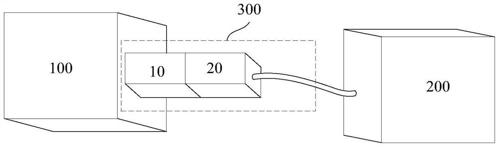
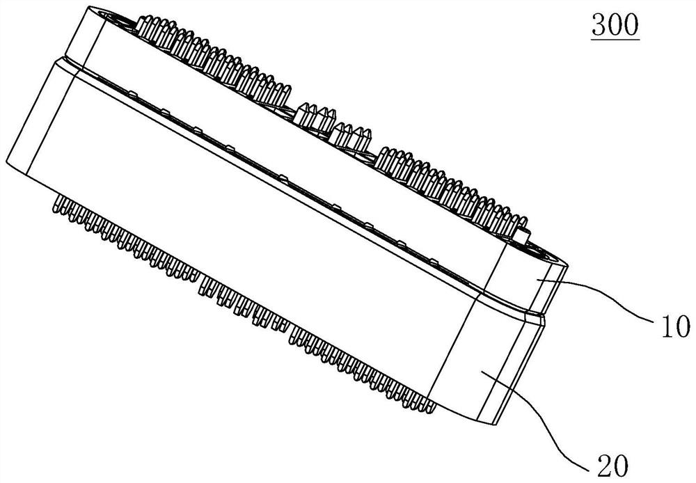
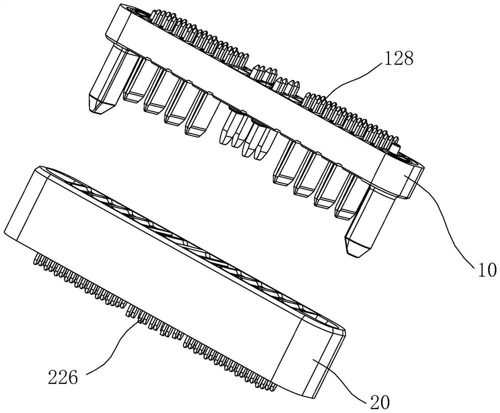
[0044] At present, by increasing the number of signal terminals having the same structure as the power supply terminals, and arranging the added signal terminals at intervals in the arrangement direction of the power supply terminals and the signal terminals, the purpose of transmitting more signals at the same time is realized. However, in this way, the size of the connector in the direction of arrangement of the power terminals and the signal terminals increases greatly, which is not conducive to the miniaturization design of the connector.

[0045] In view of the above problems, the embodiment of the present application arranges the positive terminal, the negative terminal and the signal terminal group side by side along the first direction and at intervals, and designs the width of the signal terminal to be smaller than the width of the positive terminal and smaller than the width of the negative terminal. At least two signal terminals in the terminal group are arranged at ...


PUM


Abstract

A connector (300), comprising a male head (10) and a female head (20) that are paired with each other. The male head (10) comprises a first housing (11) and an electric plug (12) that is disposed on the first housing (11). The electric plug (12) comprises positive terminals (121), negative terminals (122), and signal terminal groups (123). The positive terminals (121), the negative terminals (122), and the signal terminal groups (123) are arranged side by side along a first direction and are spaced apart on the same side of the first housing (11), and the signal terminal groups (123) are disposed between the positive terminals (121) and the negative terminals (122). The width direction of the positive terminals (121) and the negative terminals (122) is parallel to a second direction, and the first direction is substantially perpendicular to the second direction. Each signal terminal group (123) comprises at least two signal terminals (1230), the at least two signal terminals (1230) are arranged side by side along the second direction and spaced apart, the width direction of the signal terminals (1230) is parallel to the second direction, the width of the signal terminals (1230) is less than the width of the positive terminals (121) and less than the width of the negative terminals (122), each signal terminal (1230) is capable of transmitting a signal. In the connector (300), the number of signal terminals (1230) can be increased without increasing the volume, thus facilitating the miniaturized design of the connector. The present invention further relates to an unmanned aerial vehicle and assembly, battery and assembly, charger, and connector male and female heads.

Description

technical field [0001] The present application relates to the field of connectors, in particular to a connector and its male and female connectors, an unmanned aerial vehicle, a battery, and a charger. Background technique [0002] At present, the power terminal (that is, the power PIN) and the signal terminal (the signal PIN) of the connector male adopt the same structure, and the power terminal and the signal terminal are arranged at intervals. When designing a connector capable of transmitting more signals at the same time, by increasing the number of signal terminals with the same structure as the power supply terminals, and arranging the increased signal terminals at intervals in the direction of arrangement of the power supply terminals and signal terminals, simultaneous The purpose of transmitting more signals. However, in this way, the size of the connector in the direction of arrangement of the power terminals and the signal terminals increases greatly, which is no...

Claims


Application Information

Patent Timeline
Patent Type & Authority Applications(China)
IPC IPC(8): H01R13/04H01R13/10H01R24/66H01R24/76H01M50/50H02J7/00B64D27/24B64C39/02
CPCH01R13/04H01R13/10H01R24/66H01R24/76H02J7/0045H01M50/50B64D27/24B64U50/37H02J7/00H01R13/502H01M50/502H01R24/00H01R13/40H01R27/02Y02E60/10Y02T50/60
Inventor 张瑞强李日照农贵升周乐张彩辉
Owner SZ DJI TECH CO LTD
Learn More