
Assembly method of multi-stage oil cylinder

An assembly method and oil cylinder technology, which are applied in the field of oil cylinder assembly, can solve problems such as unqualified cleanliness, iron filings generated by friction at the bottom of an inner hole of a cylinder bottom of a secondary cylinder, and iron filings generated by friction at the bottom of an inner hole of a secondary cylinder block. , to achieve the effect of good assembly quality, cleanliness assurance, and scientific design

Pending Publication Date: 2021-12-17
郑煤机智鼎液压有限公司 +1
View PDF0 Cites 0 Cited by
  • Summary
  • Abstract
  • Description
  • Claims
  • Application Information

AI Technical Summary

Problems solved by technology

This assembly method has the following disadvantages: (1) When the second-stage cylinder is assembled inside the first-stage cylinder and the first-stage guide sleeve is assembled, the bottom of the second-stage cylinder will rub against the bottom of the inner hole of the first-stage cylinder. Iron filings, resulting in unqualified cleanliness; when the third-stage cylinder is assembled inside the second-stage cylinder and the second-stage guide sleeve is assembled, the bottom of the third-stage cylinder, the bottom valve and the bottom of the inner hole of the second-stage cylinder will rub against each other. iron filings, resulting in unqualified cleanliness; when the piston rod is assembled to the inside of the third-stage cylinder and the third-stage guide sleeve is assembled, the bottom of the piston rod will also rub against the bottom of the bottom inner hole of the third-stage cylinder to produce iron filings, resulting in poor cleanliness qualified
(2) When tightening the second-level guide sleeve, the second-level cylinder rotates inside the first-level cylinder at this time, which cannot meet the tightening torque and pre-tightening force requirements of the second-level guide sleeve; when tightening the third-level guide sleeve, the third-level cylinder is in the The internal rotation of the secondary cylinder cannot meet the tightening torque and pretightening force requirements of the tertiary guide sleeve

Method used


Image

  • Assembly method of multi-stage oil cylinder
  • Assembly method of multi-stage oil cylinder
  • Assembly method of multi-stage oil cylinder

Examples


Embodiment Construction

[0025] The technical solutions of the present invention will be described in further detail below through specific implementation methods.

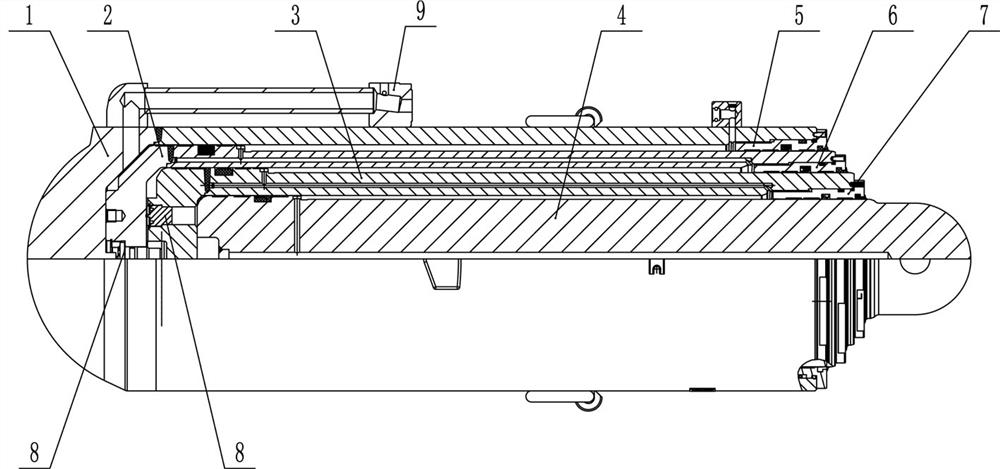
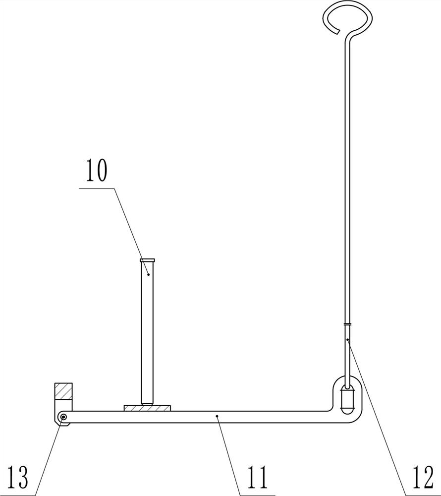
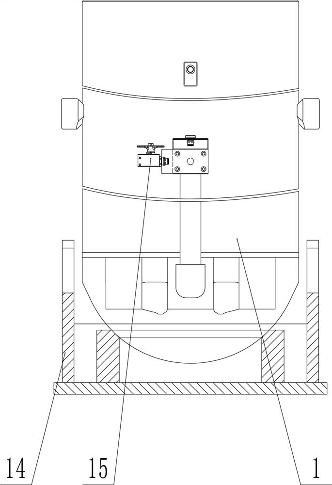
[0026] Such as Figure 1-4 As shown in the figure, an assembly method of a multi-stage oil cylinder regards the telescopic components in the cylinders of each level as a whole, and the lower-level telescopic components are directly sleeved in the upper-level cylinder. The assembly method starts from the innermost telescopic component , and assemble the cylinder blocks of all levels outward in turn, including the following cycle steps:

[0027] Step (a), place the upper cylinder block vertically with the opening facing upwards, and clamp the upper cylinder block from the outside;

[0028] Step (b), vertically drop the lower-level telescopic assembly into the upper-level cylinder. During the falling process, by controlling the connection between the inner hole of the upper-level cylinder and the outside air, the bottom end of the lower-lev...


PUM


Abstract

The invention provides an assembling method of a multi-stage oil cylinder, which is characterized in that a telescopic assembly in each stage of cylinder body is regarded as a whole, a lower-stage telescopic assembly is directly sleeved in an upper-stage cylinder body, and the assembling method is used for sequentially outwards assembling cylinder body at each stage from the innermost telescopic assembly and comprises the following circulating steps of: vertically placing the upper-stage cylinder body with an upward opening; the upper stage of cylinder body is clamped from the outer side; vertically dropping the lower-stage telescopic assembly into the upper-stage cylinder body, wherein in the dropping process, certain air is reserved between the bottom end of the lower-stage telescopic assembly and the bottom end of an inner hole of the upper-stage cylinder body by controlling connection and disconnection between the inner hole of the upper-stage cylinder body and external air, so that an isolation gap is formed; and tightening a guide sleeve between the upper-stage cylinder body and the lower-stage telescopic assembly by using specified torque. The assembling method of the multi-stage oil cylinder has the advantages that the design is scientific, the cleanliness can be guaranteed, the guide sleeve can be tightened, and the assembling quality is good.

Description

technical field [0001] The invention relates to the field of oil cylinder assembly, in particular to an assembly method of a multi-stage oil cylinder. Background technique [0002] In order to adapt to frequent changes in the thickness of the coal seam and meet the requirements of stroke and closure size, the hydraulic support columns of coal mine fully mechanized mining are generally multi-stage oil cylinders. For example, a common three-stage telescopic oil cylinder is composed of a first-stage cylinder block, a second-stage cylinder block, a third-stage cylinder block, a piston rod, a first-stage guide sleeve, a second-stage guide sleeve, a third-stage guide sleeve, a bottom valve assembly, and a sealing assembly. The bottom valve assembly is assembled on the bottom of the plunger end of the secondary cylinder and the tertiary cylinder, and the up and down movement of the ejector rod in the bottom valve controls the opening and closing of the bottom valve. [0003] The e...

Claims


Application Information

Patent Timeline
Patent Type & Authority Applications(China)
IPC IPC(8): B23P21/00
CPCB23P21/00
Inventor 孟贺超程相榜王璐白建朋印文才赵伟方张静杨法启李瑞鹏王英颖袁冰冰刘晨辉
Owner 郑煤机智鼎液压有限公司
Learn More