
Flanging riveting equipment based on engine intake manifold

A technology for intake manifolds and engines, which is applied in the field of riveting equipment for plastic shells and intercoolers, can solve the problems of difficult troubleshooting of intercoolers and large plastic shells, and reduce the time required for the process. The effect of fast and convenient loading

Pending Publication Date: 2021-12-17
长春超维智能设备制造有限公司
View PDF0 Cites 0 Cited by
  • Summary
  • Abstract
  • Description
  • Claims
  • Application Information

AI Technical Summary

Problems solved by technology

The disadvantage of putting the intercooler inside is that the plastic shell is relatively large, and the fault of the intercooler is not easy to troubleshoot

Method used


Image

  • Flanging riveting equipment based on engine intake manifold
  • Flanging riveting equipment based on engine intake manifold
  • Flanging riveting equipment based on engine intake manifold

Examples


Embodiment Construction

[0039] In the following description, for purposes of explanation, numerous specific details are set forth in order to provide a thorough understanding of one or more embodiments. It may be evident, however, that these embodiments may be practiced without these specific details. In other instances, well-known structures and devices are shown in block diagram form in order to facilitate describing one or more embodiments.

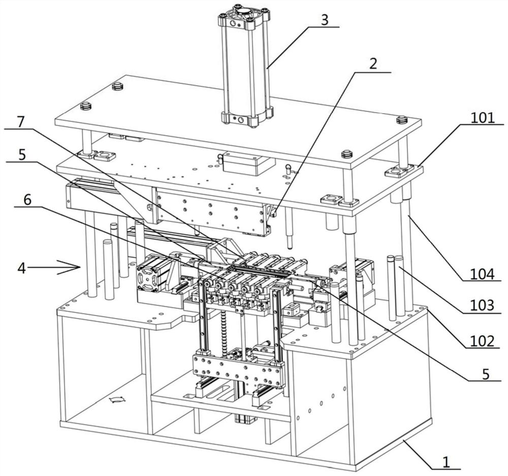
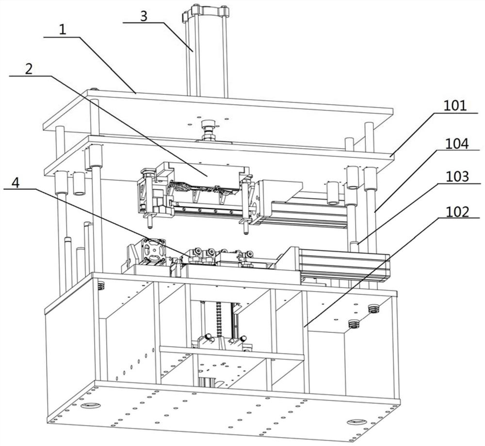
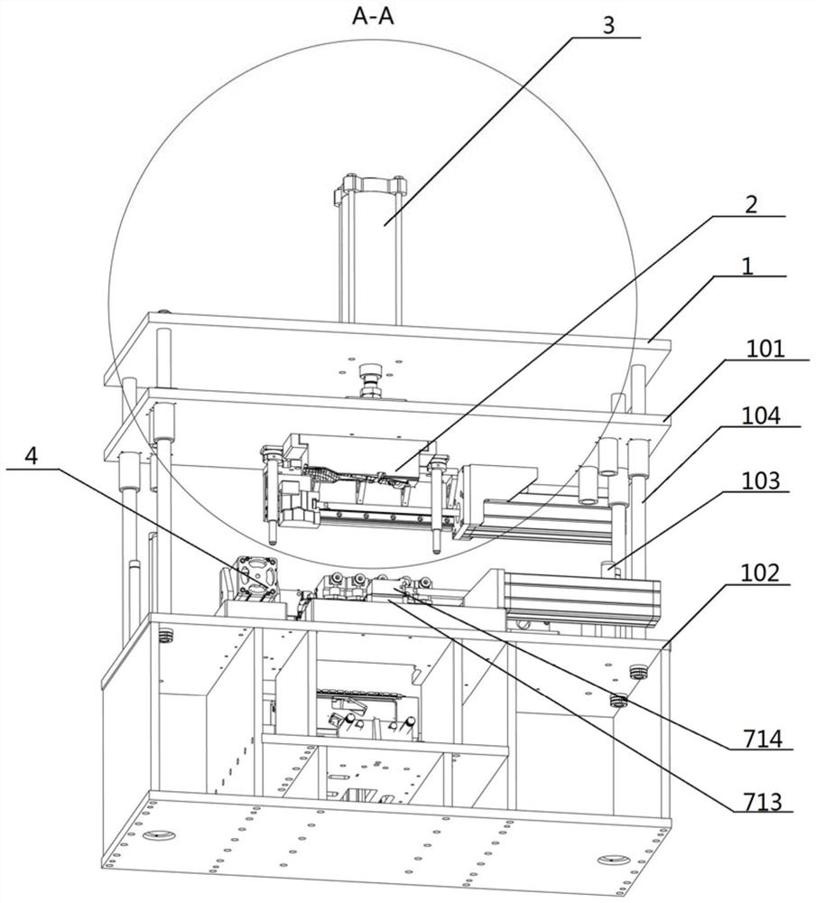
[0040] Figure 1-14 A schematic diagram of the overall structure according to an embodiment of the present invention is shown.

[0041] Such as Figure 1-14 As shown, the flanging riveting equipment based on the engine intake manifold provided by the embodiment of the present invention includes: a frame 1, a profiling tire mold 2 installed on the upper mold platform 101 of the frame 1, and a profiled tire mold 2 installed on the frame 1. And drive the upper mold driving cylinder 3 of the profiling tire mold 2, the flanging riveting device 4 installed on th...


PUM


Abstract

The invention relates to flanging riveting equipment based on an engine intake manifold. The flanging riveting equipment comprises a rack, a profiling moulding bed mounted on an upper die platform of the rack, an upper die driving air cylinder mounted on the rack and used for driving the profiling moulding bed, and a flanging riveting device mounted on a lower die platform of the rack, the flanging riveting mechanism is used for flanging riveting of a plastic shell and an intercooler, and the profiling moulding bed is used for positioning the intercooler on the flanging riveting device; and the flanging riveting device is composed of two side edge riveting mechanisms located at the two ends of the intercooler, a lifting type riveting mechanism located at the front side of the intercooler and a main riveting mechanism located at the rear side of the intercooler, and the side edge riveting mechanisms are used for flanging the side faces of the intercooler. The lifting type riveting mechanism and the main riveting mechanism are used for flanging the front side and the rear side of the intercooler; and the flanging riveting equipment has the advantages that the flanging riveting device can realize quick riveting of the intercooler and the injection molding shell, and the connecting structure is riveted, so that the manufacturing efficiency of the intake manifold is improved, and the manufacturing cost is reduced.

Description

technical field [0001] The invention relates to the technical field of riveting equipment, in particular to riveting equipment for a plastic shell of an intake manifold and an intercooler flanging. Background technique [0002] There are mainly two ways to connect the existing automobile manifold cooler and the plastic shell, one of which is connected by screws, and the other is to place the intercooler in the shell. The former is that the two ends of the cooler are connected to the housing through screws respectively, and the disadvantage is that the screws are generally more than 12. The latter is to put the intercooler inside the two shells, and then weld the two shells. Among the above two connection methods, the cost of screw connection is relatively high. The disadvantage of putting the intercooler inside is that the plastic shell is relatively large, and the fault of the intercooler is not easy to troubleshoot. Contents of the invention [0003] In view of the ab...

Claims


Application Information

Patent Timeline
IPC IPC(8): B29C65/60B29C65/64B29C65/78B21D19/08B21D37/10B29L31/30
CPCB29C65/60B29C65/64B29C65/7805B29C65/7858B21D19/08B21D37/10B29L2031/30
Inventor 吴厚虎张春生贾振宇
Owner 长春超维智能设备制造有限公司
Learn More