Check patentability & draft patents in minutes with Patsnap Eureka AI!

Visual experiment device

An experimental device and inner cavity technology, which is applied in the field of visual experimental devices, can solve the problems of large area and complicated requirements of the experimental device.

Pending Publication Date: 2021-12-17
SPECIAL EQUIP SAFETY SUPERVISION INSPECTION INST OF JIANGSU PROVINCE +1
View PDF11 Cites 0 Cited by
  • Summary
  • Abstract
  • Description
  • Claims
  • Application Information

AI Technical Summary

Problems solved by technology

[0004] At present, the test of the above data needs to be obtained through corresponding experiments with different detection devices, resulting in a large area of ​​the experimental device and cumbersome requirements, so the integrated experimental device has become a test requirement

Method used


Image

  • Visual experiment device
  • Visual experiment device
  • Visual experiment device

Examples


experiment example 1

[0065] When conducting liquid nitrogen evaporation demonstration experiments, the following steps can be followed:

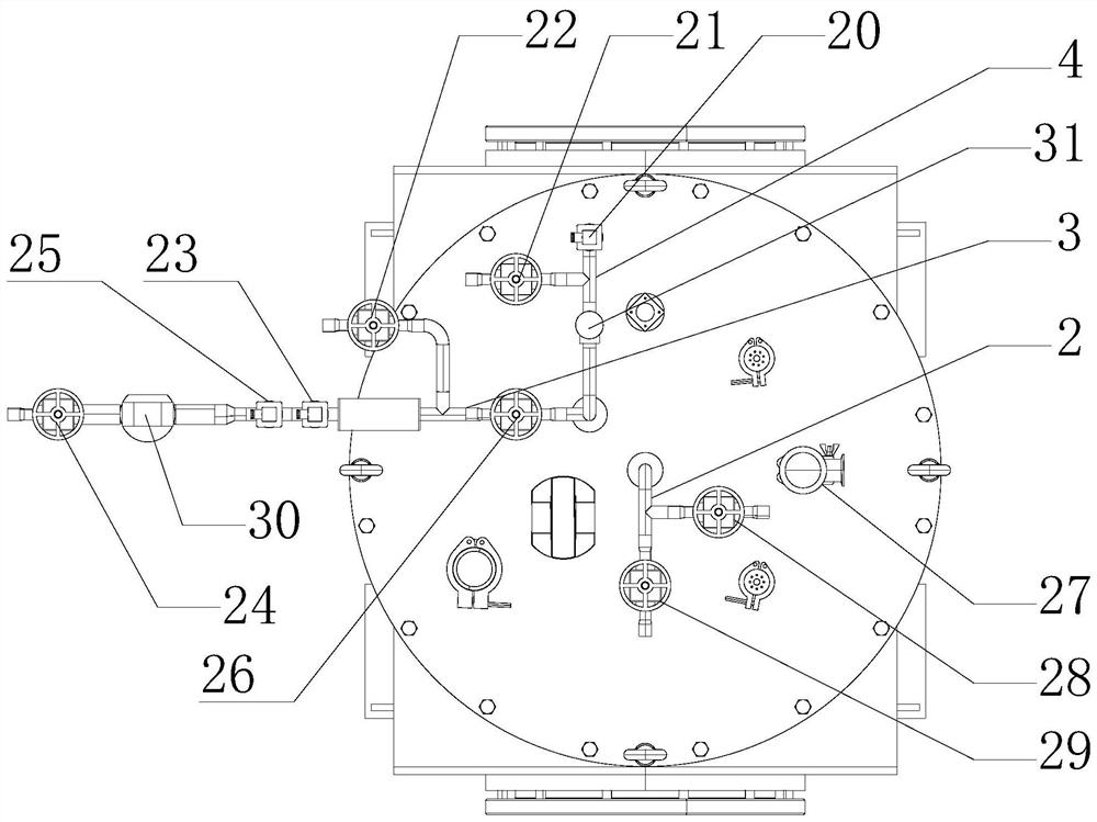
[0066] First, the molecular pump set is connected to the vacuum baffle valve 27 through the bellows to vacuumize the interlayer of the cavity;

[0067] Check the opening and closing status of each valve before filling liquid nitrogen. The third stop valve 29 of the liquid inlet line 2 and the second stop valve 21 of the exhaust line 4 are in the open state, and the other valves are closed; they are connected by corrugated hoses. The interface of the liquid nitrogen tank is connected to the interface of the liquid inlet pipeline 2, and the outlet valve of the liquid nitrogen tank is opened to inject liquid into the inner cavity cylinder 201; The liquid nitrogen in the inner cavity cylinder 201 will undergo a violent phase change and vaporize, and it will be exhausted violently after the exhaust valve. Be careful of low temperature frostbite; wait until the liquid...

experiment example 2

[0070] When performing the static evaporation rate test of the gas cylinder, the gas cylinder to be tested is connected to the 22 pipelines of the fourth shut-off valve through a metal hose, and the pipeline is turned on and heated to the required power. The temperature, pressure and flow data collected by the host computer can be Calculate the static evaporation rate.

experiment example 3

[0072] When used as a time measurement system, the gas cylinder to be tested is connected to the pipeline at the fourth stop valve 22 through a metal hose, the fourth stop valve 22 and the fifth stop valve 24 are opened, and after the gas evaporates to a certain pressure, the safety valve 31 It will take off to release the pressure, and the recorded take-off time of the safety valve 31 is the required measurement time.


PUM


Abstract

The invention relates to a visual experiment device for liquid nitrogen evaporation experiment and gas cylinder static evaporation rate test. The visual experiment device comprises a visual cavity, a liquid inlet pipeline, a discharge pipeline and an exhaust pipeline, the liquid inlet pipeline, the discharge pipeline and the exhaust pipeline are arranged on the visual cavity, the visual cavity comprises an outer cavity and an inner cavity, the outer cavity comprises an outer cavity cylinder and outer cavity observation windows arranged on two sides of the outer cavity cylinder, the inner cavity comprises an inner cavity cylinder, inner cavity observation windows which are arranged on the two sides of the inner cavity cylinder and correspond to the outer cavity observation windows, and a radiation screen arranged outside the inner cavity cylinder, and a heating piece is arranged at the bottom of the inner cavity cylinder and used for researching the liquid nitrogen evaporation effect under different heating powers. The glass observation windows are installed on the side faces of the inner cavity and the outer cavity, the static and dynamic evaporation process of the low-temperature liquid nitrogen can be displayed, and the change of the internal liquid nitrogen can be directly observed conveniently. According to the device, a liquid nitrogen evaporation demonstration experiment, the static evaporation rate of the low-temperature heat insulation gas cylinder and the maintaining time are integrated on one set of device, and the dual requirements of experiment display and on-line inspection are met.

Description

technical field [0001] The invention relates to an experimental device, in particular to a visual experimental device for liquid nitrogen evaporation experiment and gas cylinder static evaporation rate test. Background technique [0002] At present, the use of cryogenic liquid has entered all walks of life, from scientific research to national defense industry to civilian enterprises, the demand for cryogenic liquid is increasing. Safe, economical and efficient storage of cryogenic liquids is a prerequisite for the rapid and healthy development of the cryogenic liquid industry. In a general sense, any equipment that can be used for cryogenic liquid storage can be called cryogenic insulation equipment. [0003] Cryogenic gas cylinders are one of the main storage devices for storing cryogenic liquids, and the static evaporation rate and maintenance time are important parameters to characterize the thermal insulation performance of cryogenic gas cylinders. [0004] At present...

Claims


Application Information

Patent Timeline
IPC IPC(8): G01N25/12
CPCG01N25/12
Inventor 沈俊苏文娟岳云飞李昊孙大明沈惬
Owner SPECIAL EQUIP SAFETY SUPERVISION INSPECTION INST OF JIANGSU PROVINCE
Features
  • R&D
  • Intellectual Property
  • Life Sciences
  • Materials
  • Tech Scout
  • Unparalleled Data Quality
  • Higher Quality Content
  • 60% Fewer Hallucinations
Learn More