
Wafer clamping fixture

A fixture and claw technology, applied in the field of mechanical fixtures, can solve problems such as wafer slipping and cracking, operator's hand burns, and operations that cannot be standardized and standardized, so as to prevent slipping and cracking, reduce wafer pollution, and protect safe effect

Pending Publication Date: 2021-12-17
威科赛乐微电子股份有限公司
View PDF0 Cites 1 Cited by
  • Summary
  • Abstract
  • Description
  • Claims
  • Application Information

AI Technical Summary

Problems solved by technology

Such a transfer method is likely to cause the operator's hands to burn or the risk of the wafer slipping and breaking
The operation is not standardized and standardized

Method used


Image

  • Wafer clamping fixture
  • Wafer clamping fixture
  • Wafer clamping fixture

Examples


Embodiment Construction

[0032] The following will clearly and completely describe the technical solutions in the embodiments of the present invention with reference to the accompanying drawings in the embodiments of the present invention. Obviously, the described embodiments are only part of the embodiments of the present invention, not all of them. Based on the embodiments of the present invention, all other embodiments obtained by persons of ordinary skill in the art without creative efforts fall within the protection scope of the present invention.

[0033] It should be noted that if there is a directional indication (such as up, down, left, right, front, back...) in the embodiment of the present invention, the directional indication is only used to explain the position in a certain posture (as shown in the accompanying drawing). If the specific posture changes, the directional indication will also change accordingly.

[0034] In addition, if there are descriptions involving "first", "second" and ...


PUM


Abstract

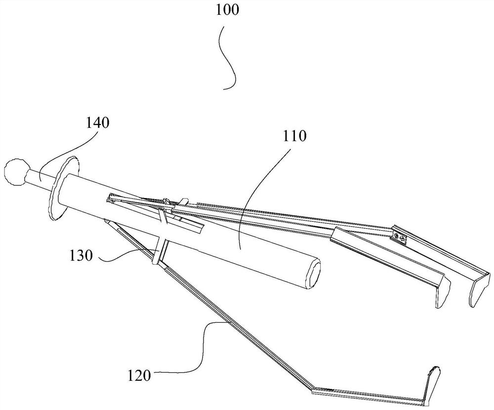
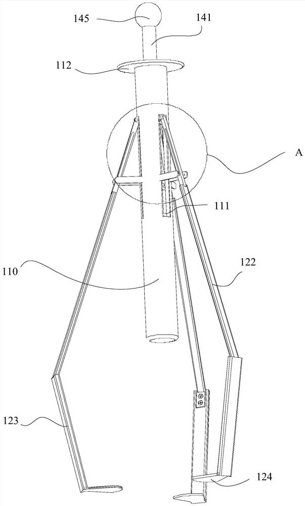
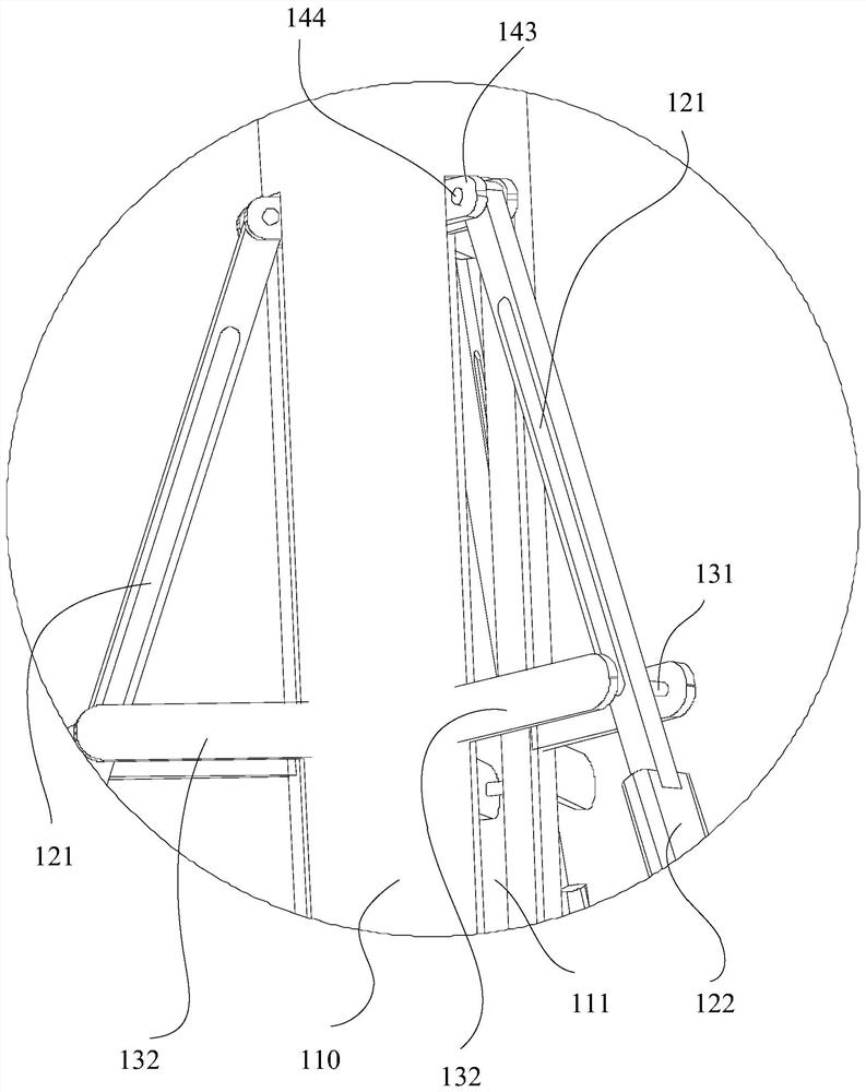
The invention relates to the technical field of mechanical jigs, and discloses a wafer clamping fixture which comprises a barrel, at least three clamping jaws, at least three supporting assemblies and a driving assembly. A sliding groove is formed in each clamping jaw; each supporting assembly is fixedly connected with the barrel, the supporting assembly and the clamping jaw are arranged correspondingly, the supporting assembly comprises a supporting shaft, and part of the supporting shaft is arranged in the sliding groove; and one end of the clamping jaw is rotationally connected with the driving assembly. According to the technical scheme, the barrel, the at least three clamping jaws, the at least three supporting assemblies and the driving assembly are adopted, so that the function of rapidly transferring wafers is achieved; the problems of nonstandardization and safety in wafer transfer after de-bonding are solved; and the safety of operators is protected, the wafers are prevented from slipping off and being broken, the working efficiency of wafer production is improved, and wafer pollution caused by operation is reduced.

Description

technical field [0001] The invention relates to the technical field of mechanical jigs, in particular to a jig for clamping wafers. Background technique [0002] At present, in the process of chip production, it is necessary to thin and grind the preliminarily formed wafer. Before grinding, the wafer needs to be bonded to sapphire, and then the wafer needs to be ground. After the grinding is completed, the wafer needs to be debonded to separate the wafer from the sapphire. Debonding requires the use of a debonding machine. The wafer is placed on a silicon wafer larger than the wafer size and placed above the equipment stage. Debonding is to conduct the temperature to the sapphire and the wafer by heating the stage, so that the sapphire and wafer The adhesive between them melts, so as to achieve the effect that the wafer is separated from the sapphire. After the debonding is completed, there is still adhesive residue on the surface of the wafer, which needs to be transferre...

Claims


Application Information

Patent Timeline
Patent Type & Authority Applications(China)
IPC IPC(8): H01L21/687
CPCH01L21/68707
Inventor 平登宏彭鹏陈丽祥王敬
Owner 威科赛乐微电子股份有限公司
Learn More