Supercharge Your Innovation With Domain-Expert AI Agents!

Transformer substation switching control system and method

A technology of a control system and a control method, which is applied in the field of intelligent substations, can solve the problems of insufficient technical level, endangering the life of operators, power grid safety, and misoperation.

Pending Publication Date: 2021-12-17
GUANGDONG POWER GRID CO LTD +1
View PDF0 Cites 0 Cited by
  • Summary
  • Abstract
  • Description
  • Claims
  • Application Information

AI Technical Summary

Problems solved by technology

Whether it is because the operating personnel did not operate item by item according to the dispatch order, strictly abide by the switching operation process, or out of carelessness, they did not rigidly execute the operation ticket, or due to insufficient technical level, they operated blindly because they knew little about the equipment to be operated. etc., may lead to misoperation, and in serious cases will endanger the life of the operating personnel and the safety of the entire power grid

Method used


Image

  • Transformer substation switching control system and method
  • Transformer substation switching control system and method
  • Transformer substation switching control system and method

Examples


Embodiment 1

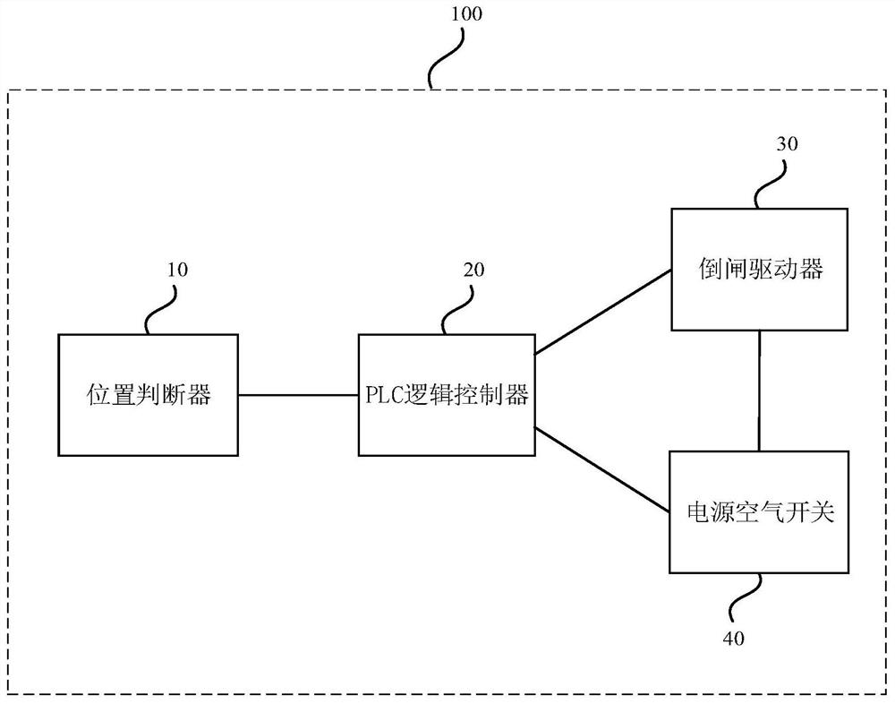
[0037] figure 1 It is a schematic structural diagram of a substation switching control system provided by an embodiment of the present invention. This embodiment is applicable to an application scenario in which a PLC control program is used to automatically perform a line switching operation.

[0038] Such as figure 1 As shown, the substation switch control system 100 includes: a position judger 10 , a PLC logic controller 20 , a switch driver 30 and a power supply air switch 40 . The position judging device 10 is electrically connected with the PLC logic controller 20, and is used for judging the state of the line switch and the knife switch in the primary equipment; the PLC logic controller 20 is used for judging whether the knife switch has an operation according to the state of the line switch and the knife switch in the primary equipment. Conditions, if the PLC logic controller 20 judges that the knife switch has the operating conditions, it will control the power suppl...

Embodiment 2

[0081] Embodiment 2 of the present invention provides a substation switching control method, Figure 5 It is a flow chart of a substation switching control method provided by Embodiment 2 of the present invention. Such as Figure 5 As shown, the substation switching control method includes the following steps:

[0082] S110. The position judger judges the state of the line switch and the knife switch in the primary equipment;

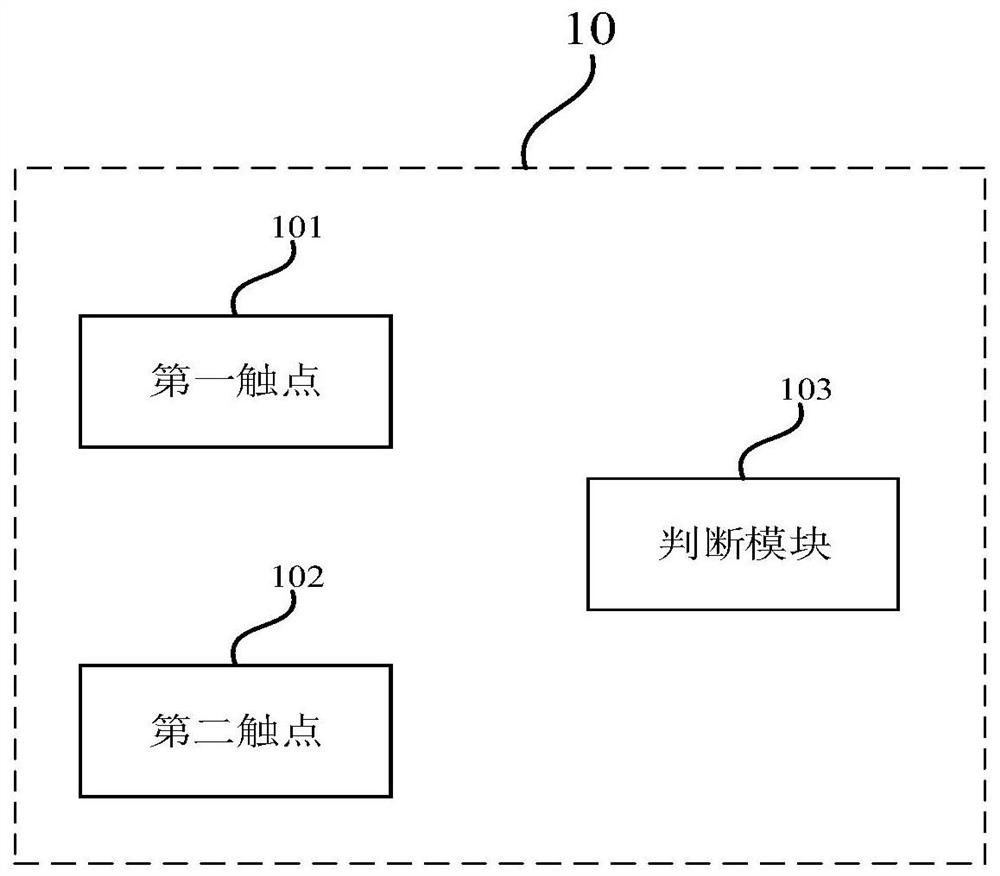
[0083] Specifically, the position judging device refers to the auxiliary contact in the control circuit, which is electrically connected with the PLC logic controller. The opening or closing of the knife switch will correspond to different contact closures, so as to judge the status of the knife switch in the primary equipment.

[0084] S120. The PLC logic controller judges whether the knife switch meets the operating conditions according to the state of the line switch and the knife switch in the primary equipment;


PUM


Abstract

The embodiment of the invention discloses a transformer substation switching control system and method. The control system comprises a position judging device, a PLC, a power supply air switch and a switching driver, wherein the position judging device is electrically connected with the PLC and is used for judging the states of a line switch and a knife switch in primary equipment, the PLC is used for judging whether the knife switch has an operation condition according to the judgment result of the position judging device, if the PLC judges that the knife switch has the operation condition, the PLC controls the power supply air switch to be closed and controls the switching driver to carry out switching operation, otherwise, the PLC executes interruption operation, and the power supply air switch is electrically connected with the switching driver and is used for controlling whether the switching driver is connected with a power supply signal or not. According to the embodiment of the invention, the circuit switching operation is automatically executed through the PLC control program, so that the automation level of the transformer substation can be improved, misoperation caused by human factors can be better avoided, the operation cost is saved, and safe and stable operation of the transformer substation is ensured.

Description

technical field [0001] Embodiments of the present invention relate to the technical field of intelligent substations, in particular to a substation switching control system and method. Background technique [0002] Smart substations are an important part of smart grids. The focus of development in the field of power transformation is smart substations. Smart substations will play a pioneering role in the construction of smart grids. The switching operation of primary and secondary equipment is an important link that restricts the development of smart substations. The switching operation involves the transition of the state of electrical equipment, which generally starts with the dispatching order. From the operator receiving the dispatching order to the completion of the entire operation process, there are danger points in every link; due to the variety of substation equipment and many influences during the operation process Factors, so dangerous points generally exist in t...

Claims


Application Information

Patent Timeline
Patent Type & Authority Applications(China)
IPC IPC(8): H02J13/00H02H7/22
CPCH02J13/00022H02J13/0004H02H7/22Y02E60/00Y04S10/16Y04S10/20Y04S40/126
Inventor 郑跃斌郑晓滨刘铠滢谢伟宏陈振昕戴美胜谢培鑫朱森耿蔡煜瑞江晓敏龙小琦
Owner GUANGDONG POWER GRID CO LTD
Features
  • R&D
  • Intellectual Property
  • Life Sciences
  • Materials
  • Tech Scout
  • Unparalleled Data Quality
  • Higher Quality Content
  • 60% Fewer Hallucinations
Learn More