Control system of brushless direct current variable frequency motor
A DC frequency conversion motor and control system technology, applied in the direction of single motor speed/torque control, starting device, etc., can solve the problems of waste of electric energy, difficulty in starting, etc., and achieve the goal of avoiding the dead point position, ensuring the rotation effect, and ensuring the effect Effect
- Summary
- Abstract
- Description
- Claims
- Application Information
AI Technical Summary
Problems solved by technology
Method used
Image
Examples
Embodiment 1
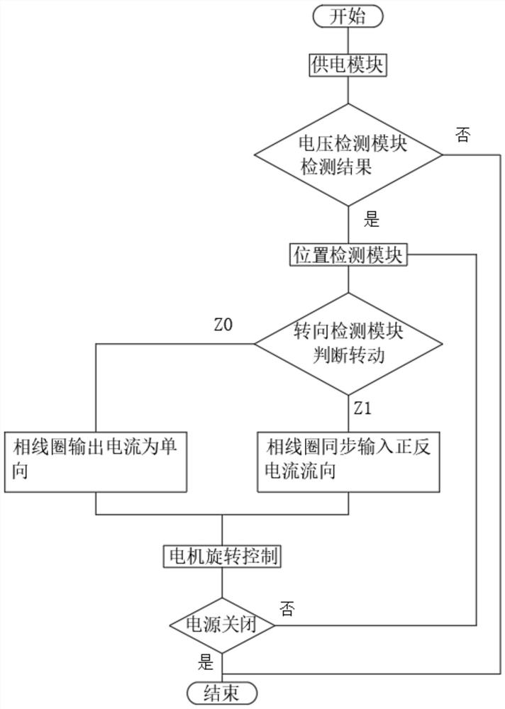
[0049] refer to figure 2 , the starting steps of the brushless DC variable frequency motor include:
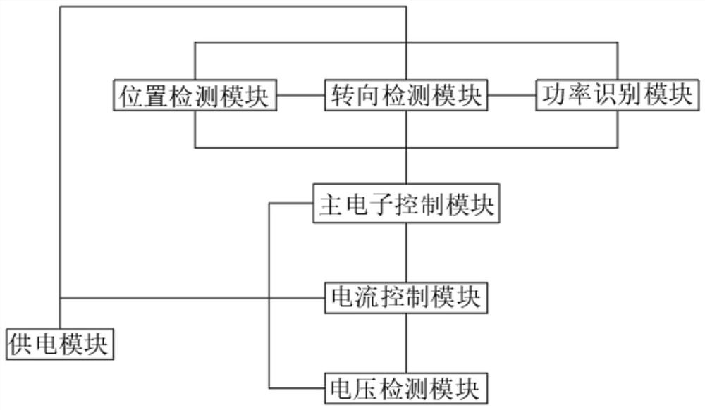
[0050] S1. The main electronic control module receives the start command, the power supply module supplies power to the system, and at the same time, the position detection module detects the position status of the permanent magnet of the rotor, judges the N-level and S-level positions of the permanent magnet, and transmits the position information to the main electronic control module;
[0051] S2. The steering detection module detects the initial state of the rotor. If the initial state of the rotor is rotating, the output result is Z1. If the initial state of the rotor is stationary, the output result is Z0, and the rotating state of the rotor is transmitted to the electronic main control module;
[0052] S3. The main control unit of the main electronic control module receives the position information, and according to the N-level and S-level position information of the pe...
Embodiment 2
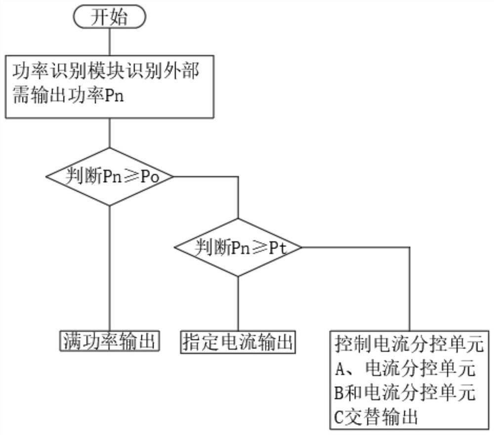
[0057] refer to image 3 , when the brushless DC variable frequency motor rotates or starts, it also includes judging the output power, and the specific steps include:
[0058] D1. The power identification module identifies the external required output power, determines the size of the power Pn, and transmits the power information to the main electronic control module.
[0059] D2. The power pairing unit of the main electronic control module is preset with a first threshold Po and a second threshold Pt. The main control unit performs a logical comparison between the received power Pn and the set first threshold and second threshold. When Pn≥Po, Then control the full power output of the current control module. When Po>Pn≥Pt, the current control module specifies the current output. When Pn<Pt, the current control module controls the phase coil and the phase coil of the permanent magnet to energize;
[0060] D3. The current control unit receives the pairing information and contr...
PUM
 Abstract
Description
Claims
Application Information
 - R&D
- Intellectual Property
- Life Sciences
- Materials
- Tech Scout
- Unparalleled Data Quality
- Higher Quality Content
- 60% Fewer Hallucinations
Browse by: Latest US Patents, China's latest patents, Technical Efficacy Thesaurus, Application Domain, Technology Topic, Popular Technical Reports.
© 2025 PatSnap. All rights reserved.Legal|Privacy policy|Modern Slavery Act Transparency Statement|Sitemap|About US| Contact US: help@patsnap.com


