Cup sleeve taking-out and stacking tool

A cup sleeve and tooling technology, which is applied in the field of cup sleeve removal and stacking tooling, can solve problems such as excessive sweating, cup sleeve surface adhesion, etc., and achieve the effects of multiple benefits, short molding cycle, and enlarged anti-vibration effect.

Active Publication Date: 2021-12-21
遵义遵道智造实业有限公司
View PDF4 Cites 0 Cited by
  • Summary
  • Abstract
  • Description
  • Claims
  • Application Information

AI Technical Summary

Problems solved by technology

[0004] Aiming at the deficiencies of the prior art, the present invention provides a tool for taking out and stacking the cup sleeves, which solves the problem of excessive sweat stains attached to the surface of the cup sleeves due to excessive finishing actions , fingerprints, etc.

Method used


Image

  • Cup sleeve taking-out and stacking tool
  • Cup sleeve taking-out and stacking tool
  • Cup sleeve taking-out and stacking tool

Examples


Embodiment 1

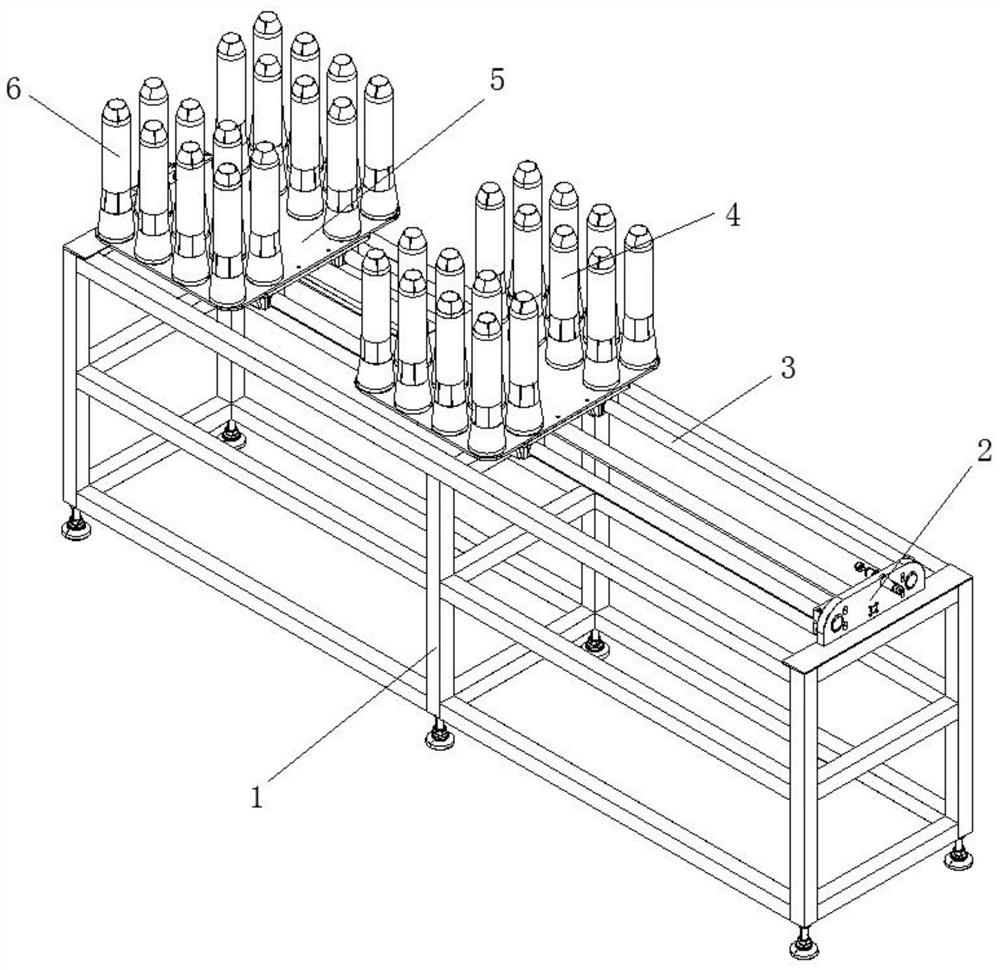
[0033] Such as Figure 1-3 As shown, the present invention provides a technical solution: a cup sleeve removal and stacking tool, including a frame 1, the top of the frame 1 is fixedly connected with a station exchange device 2, and the station exchange device 2 The interior is fixedly connected with a solenoid valve driving cylinder mechanism 3, and the top of the solenoid valve driving cylinder mechanism 3 is slidably connected with a backing plate device 5, and the top of the backing plate device 5 is fixedly connected with A station 6 and B station 4 respectively. ;

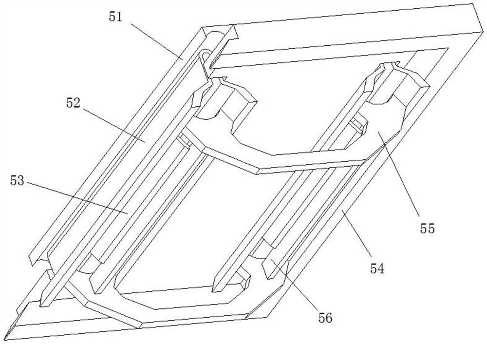
[0034] The backing plate device 5 includes a socket pressing plate 54, an outer supporting folded plate 52 is sleeved inside the sleeve pressing plate 54, and an upper load-bearing backing plate 51 is sleeved on the top of the outer supporting folded plate 52. The upper load-bearing backing plate 51 is fixedly connected under the A station 6 and the B station 4 . The number of times the manipulator complete...

Embodiment 2

[0043] Such as Figure 4-5 As shown, on the basis of Embodiment 1, the present invention provides a technical solution: the B station 4 includes a cup collar bar 401, and the outer surface of the cup collar bar 401 is fixedly connected with a sleeve orifice plate 405 , the outer surface of the sleeve hole plate 405 is provided with an outer cooling hole 403 , and the depression on the outer surface of the cup collar rod 401 is provided with an elastic rubber plate 402 .

[0044] The outer surface of the bottom of the cup collar bar 401 is fixedly connected with a collar 404, the collar 404 is arranged on the outer surface of the elastic rubber plate 402, and the inner surface of the cup collar bar 401 is fixedly connected with a vibration device 410 A rotating shaft 406 is sheathed in the inner cavity of the cup sleeve ring rod 401 .

[0045] The end of the rotating shaft 406 is fixedly connected with a rotating plate 407, the outer surface of the rotating plate 407 is fixedl...

Embodiment 3

[0049] Such as Image 6 As shown, on the basis of Embodiment 1 and Embodiment 2, the present invention provides a technical solution: the vibration device 410 includes a vibration bending piece 4101 and an outer bonding plate 4103, and the vibration bending piece 4101 and the outer bonding plate 4103 An internal pressure air bag 4102 is provided between the opposite surfaces, and an elastic strut 4106 is fixedly connected to the inside of the outer lamination plate 4103 .

[0050] The outer surface of the outer bonding plate 4103 is sleeved with a sliding sleeve shaft 4104 , and the bottom of the sliding sleeve shaft 4104 is fixedly connected with a friction brush 4105 , and the elastic strut 4106 is extruded and fitted with the vibrating bending piece 4101 . The friction brush 4105 can fit and scrape the inner surface of the cup cover when the vibration bending piece 4101 vibrates, and the contact area between the cup cover and the outer bonding plate 4103 can be reduced by t...


PUM


Abstract

The invention discloses a cup sleeve taking-out and stacking tool, and releates to the technical field of injection molding manufacturing. The cup sleeve taking-out and stacking too comprises a rack, a station interchanging device is fixedly connected to the top of the rack, an electromagnetic valve driving air cylinder mechanism is fixedly connected to the interior of the station interchanging device, a base plate device is slidably connected to the top of the electromagnetic valve driving air cylinder mechanism, the top of the base plate device are correspondingly connected to a working station A and a working station B, and the base plate device comprises a cup joint pressing device. According to the cup sleeve taking-out and stacking tool, an electromagnetic signal is given to the electromagnetic valve driving air cylinder mechanism through the times which a manipulator takes out cup sleeves and completes the stacking of the working station A, when the working station B runs to the position of the working station A, the manipulator takes the cup sleeves and continues to stack the cup sleeves for the set times of the manipulator, after the stacking times of the working station B are completed, the manipulator sends a signal to the electromagnetic valve driving air cylinder mechanism to push the working station A to the original position, the manipulator continues to stack, and the process is circulated, so that the recycling effect of the device is achieved.

Description

technical field [0001] The invention relates to the technical field of injection molding, in particular to a tool for removing and stacking cup sleeves. Background technique [0002] The beverage market in the global livelihood consumer market has developed so far, and there are so many types, and the new tea drink market is booming. In recent years, with the growth of per capita disposable income and the continuous improvement of willingness and ability to pay, new tea drinks cater to the individual needs of consumption upgrades, showing a trend of quality upgrades, rich scenes, diverse needs, and equal emphasis on products and services. The required packaging materials are even more diverse, among which cup sleeves are an integral part of tea packaging materials. However, there are still many problems in the production process of cup sleeves, among which the problem of inability to stack requires a lot of labor, and at the same time, too many finishing actions cause exces...

Claims


Application Information

Patent Timeline
Patent Type & Authority Applications(China)
IPC IPC(8): B29C45/17
CPCB29C45/1769B29C2045/177
Inventor 罗良山
Owner 遵义遵道智造实业有限公司
Why Eureka
Try Eureka