
Method and system for blowing off floating ice in ballast water tank through hot air of marine engine room

A ballast water tank and hot air technology, applied in hull ventilation/heating/cooling, ship components, ship construction, etc., can solve the problems of ship safety navigation threats, increased emissions, poor anti-icing effect, etc., to improve energy Use efficiency, reduce energy consumption, and avoid water freezing effects

Pending Publication Date: 2021-12-21
WUHAN UNIV OF TECH
View PDF7 Cites 0 Cited by
  • Summary
  • Abstract
  • Description
  • Claims
  • Application Information

AI Technical Summary

Problems solved by technology

However, when the ship is sailing in the polar environment, the ballast water in the ballast water tank will freeze due to the influence of the low temperature environment, resulting in the ballast water cannot be transferred normally, which poses a huge threat to the safe navigation of the ship
[0003] In the prior art, the polar ships use the foam blowing system to prevent the ballast water from freezing. At present, there are two main types of foam blowing systems: one is to use a low-pressure air pump to directly pump the air in the air chamber to the ballast through the air pipeline. In the water tank, one end of the air pipe is connected to the low-pressure air source device, and the other end directly extends to the bottom of the ballast tank. This kind of bubble blowing system not only requires an additional air chamber, but also takes up space on the ship. The important thing is that the formed bubbles are also Small, poor anti-icing effect; another method is to install a compressor on the side of the ballast tank, and send the air source into the ballast water tank along the air pipeline through the compressor. This method requires an additional compressor Use cost, and the compressor will generate a lot of energy consumption when working, increasing emissions

Method used


Image

  • Method and system for blowing off floating ice in ballast water tank through hot air of marine engine room

Examples


Embodiment Construction

[0018] The following will clearly and completely describe the technical solutions in the embodiments of the present invention with reference to the accompanying drawings in the embodiments of the present invention. Obviously, the described embodiments are only some, not all, embodiments of the present invention. Based on the embodiments of the present invention, all other embodiments obtained by persons of ordinary skill in the art without creative efforts fall within the protection scope of the present invention.

[0019] It should be noted that, in the case of no conflict, the embodiments of the present invention and the features in the embodiments can be combined with each other.

[0020] The present invention will be further described below in conjunction with the accompanying drawings and specific embodiments, but not as a limitation of the present invention.

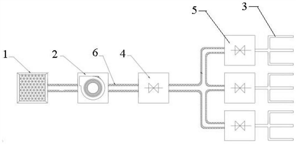
[0021] Such as figure 1 As shown, the deicing system provided in the embodiment of the present invention includ...


PUM


Abstract

The invention relates to a method and a system for blowing off floating ice in a ballast water tank by using hot air in a marine engine room. The method comprises the following steps that impurities in the hot air in the marine engine room are filtered, and the hot air is blown into the ballast water tank by using an air blower so that ballast water forms eddy current; therefore, water in the water ballast space is prevented from being frozen, and floating ice which is possibly generated is further melted through the hot air. The method is advantaged in that the temperature of the ballast tank and the temperature of ballast water in the ballast tank are increased through air waste heat in the marine engine room, so the anti-icing effect is achieved, low-grade heat in the marine engine room can be effectively utilized in the deicing mode, and therefore ship energy utilization efficiency is improved, and emission is reduced.

Description

technical field [0001] The invention relates to the technical field of polar ships, in particular to a method and a system for blowing off ice floes in ballast water tanks by using hot air in engine rooms of ships. Background technique [0002] The ballast water tank in the ship has the functions of adjusting the draft of the ship, maintaining the stability of the ship, reducing the sway of the ship, and reducing the vibration of the ship during the operation of the ship. Polar ships can also change the draft of the bow by adjusting ballast water to break ice. However, when the ship is sailing in the polar environment, the ballast water in the ballast water tank will freeze due to the influence of the low temperature environment, resulting in the inability to transfer the ballast water normally, which poses a huge threat to the safe navigation of the ship. [0003] In the prior art, the polar ships use the foam blowing system to prevent the ballast water from freezing. At p...

Claims


Application Information

Patent Timeline
IPC IPC(8): B63B39/03B63J2/14
CPCB63B39/03B63J2/14
Inventor 徐立丁正强蔡唯刘越叶培杰
Owner WUHAN UNIV OF TECH
Learn More