

Bearing retainer, rolling ball bearing and motor
A technology for bearing cages and rolling ball bearings, applied to bearing elements, shafts, bearings, shafts, etc., can solve the problems of uncompact sealing structure, oil seal easy to fall off, and normal operation of the motor, so as to achieve compact structure, avoid easy falling off, shorten The effect of length
- Summary
- Abstract
- Description
- Claims
- Application Information
AI Technical Summary
Problems solved by technology
Method used
Image

Examples
Embodiment 1
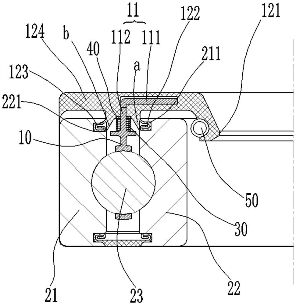
[0036] In this embodiment a bearing cage is provided, such as Figure 1-Figure 5 As shown, the cage 10 has a support portion 11 along one side of its axial direction, and the support portion 11 is covered with a sealing body 12, and the sealing body 12 is used to seal the inner ring 21 and the inner ring 21 of the bearing 20. In the gap between the outer rings 22 , the sealing body 12 is provided with a shaft seal installation hole 121 , and the shaft seal installation hole 121 is coaxially arranged with the cage 10 .
[0037] Optionally, the sealing body may be rubber.
[0038] Preferably, an annular spring 50 is embedded in the sealing body 12, and the annular spring 50 is arranged coaxially with the shaft seal installation hole 121 and is located at the position of the shaft seal installation hole 121 to ensure that the shaft seal installation hole 121 and the shaft seal installation hole Sealed shaft surfaces fit together.
[0039]Specifically, the sealing body 12 has an...
Embodiment 2
[0048] The present invention provides a rolling ball bearing, including the bearing cage described in Embodiment 1.
[0049] Specifically, such as image 3 and Figure 5 As shown, the rolling ball bearing further includes: an inner ring 21; ball rolling elements 23, the cage 10 is provided with a plurality of pockets c along its circumference, and each pocket c is provided with a ball rolling element 23 The outer ring 22 is coaxially sleeved on the inner ring 21, an annular gap is formed between the outer ring 22 and the inner ring 21, and a plurality of The ball rolling element 23, the cage 10 is arranged in the annular gap.
[0050] Further, the outer surface of the inner ring 21 is provided with a first annular sealing groove 211 coaxial therewith, and the inner ring sealing part 122 is sealingly embedded in the first annular sealing groove 211; the outer ring 22 The outer circular surface is provided with a second annular sealing groove 221 coaxial therewith, and the ou...
Embodiment 3
[0054] The present invention provides a motor, including the rolling ball bearing described in Embodiment 2.
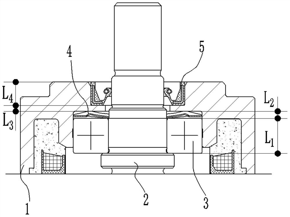
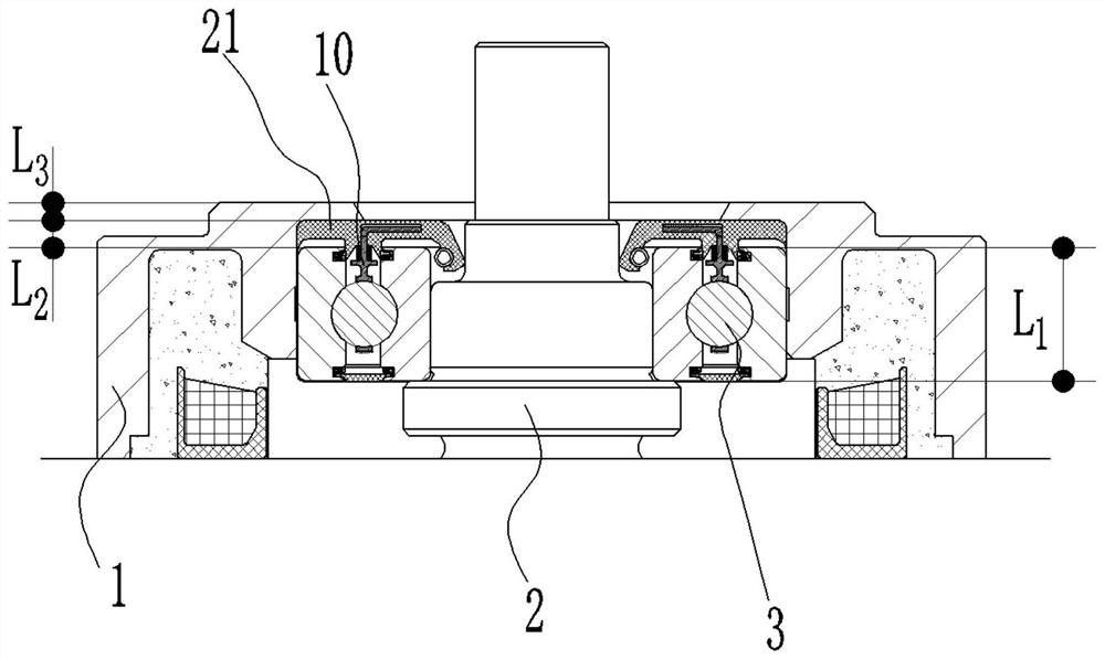
[0055] Such as figure 2 As shown, the motor also includes: a machine base 1, the front end of which is provided with a bearing shoulder c; a motor shaft 2, which is rotatably mounted on the machine base 1 through the rolling ball bearing 3, and the The end face sealing portion 124 on the bearing cage is in sealing contact with the shoulder c, and the shaft seal mounting hole 121 is in sealing fit with the motor shaft 2 .
[0056] By the formula:
[0057]
[0058]
[0059] Among them, RA—represents the thermal resistance per unit area, δ—represents the thickness of the thermally conductive material, λ—represents the thermal conductivity (thermal conductivity), φ—represents the heat flow through a given area A per unit time, θ—represents the thermal conductivity of the material end temperature difference.
[0060] From the above formulas (1) and (2), it can be...
PUM
 Abstract
Description
Claims
Application Information