
Force control method and force control system of linear switched reluctance motor

A switched reluctance motor and linear technology, applied in control systems, AC motor control, electrical components, etc., can solve problems such as large thrust fluctuations, and achieve the effect of stable output force

Pending Publication Date: 2021-12-21
CREATING CHANGE THROUGH TECH
View PDF0 Cites 0 Cited by
  • Summary
  • Abstract
  • Description
  • Claims
  • Application Information

AI Technical Summary

Problems solved by technology

[0006] The purpose of the present invention is to provide a force control method and force control system of a linear switched reluctance motor to solve the technical problem of large thrust fluctuations in the prior art

Method used


Image

  • Force control method and force control system of linear switched reluctance motor
  • Force control method and force control system of linear switched reluctance motor
  • Force control method and force control system of linear switched reluctance motor

Examples


Embodiment Construction

[0026] In order to make the purpose, technical solution and advantages of the present application clearer, the present application will be further described in detail below in conjunction with the accompanying drawings and specific embodiments. It should be understood that the specific embodiments described here are only used to explain the present application, and are not intended to limit the present application.

[0027] In order to make the description of the present disclosure more detailed and complete, the following provides an illustrative description of the implementation modes and specific examples of the present application; but this is not the only form for implementing or using the specific examples of the present application. The description covers features of various embodiments as well as method steps and their sequences for constructing and operating those embodiments. However, other embodiments can also be used to achieve the same or equivalent functions and ...


PUM


Abstract

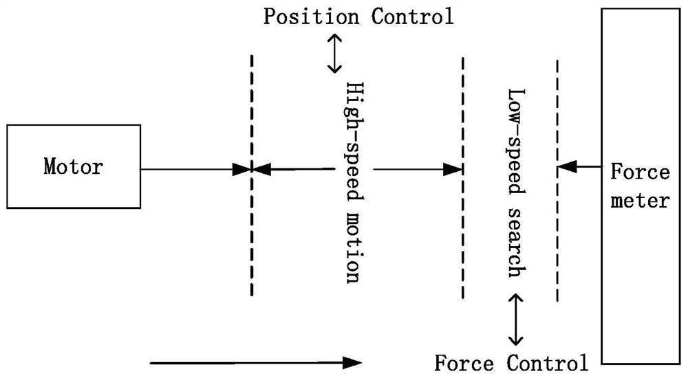
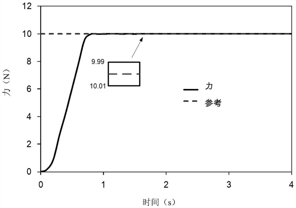
The invention relates to the technical field of linear switched reluctance motor control, in particular to a force control method and a force control system of a linear switched reluctance motor. The method comprises the steps that in the process that the linear switched reluctance motor approaches a machining target, obtaining the actual position, speed and current of the linear switched reluctance motor; judging whether the linear switched reluctance motor reaches or exceeds a preset contact condition according to the actual position and the speed condition; when the judgment result is yes, indicating that the linear switched reluctance motor is in contact with the target; and after the linear switched reluctance motor is in contact with the target, limiting the output force of the linear switched reluctance motor according to the output strategy, and then controlling the output of the force. According to the force control method and system of the linear switched reluctance motor, after the linear switched reluctance motor reaches the contact condition, the linear switched reluctance motor enters the force control mode, and the output force is limited by limiting the output current of the motor, so that the output force of the motor and the target is stable, and the force control effect is achieved.

Description

【Technical field】 [0001] The invention relates to the technical field of linear switched reluctance motor control, in particular to a force control method and a force control system of a linear switched reluctance motor. 【Background technique】 [0002] The linear switched reluctance motor is a transmission device that directly converts electrical energy into linear motion mechanical energy without any intermediate conversion mechanism. Widely used in modern processing industries, such as laser cutting, high-speed grinding machines, precision lathes, machining centers, etc., all require high-precision linear motion. [0003] The external output of the linear switched reluctance motor is mainly thrust. Due to the theory, design, manufacture, load and interference of the linear switched reluctance motor, there are thrust fluctuations in the linear switched reluctance motor. [0004] The linear switched reluctance motors in the prior art generally switch hard through position / f...

Claims


Application Information

Patent Timeline
IPC IPC(8): H02P23/00H02P25/064H02P25/08
CPCH02P23/0004H02P25/064H02P25/08
Inventor 金帅邹宇李思阳
Owner CREATING CHANGE THROUGH TECH
Learn More