Workpiece positioning method, workpiece positioning device and groove cutting workstation

A positioning method and technology for positioning position, which can be applied to workpiece clamping devices, manufacturing tools, manipulators, etc., can solve problems such as limited positioning accuracy of workpieces, and achieve the effects of ensuring accuracy, eliminating positioning errors, and accurate positions

Active Publication Date: 2021-12-24
三一机器人装备(西安)有限公司
View PDF6 Cites 2 Cited by
  • Summary
  • Abstract
  • Description
  • Claims
  • Application Information

AI Technical Summary

Problems solved by technology

[0003] Therefore, the technical problem to be solved by the present invention is to overcome the defect of limited workpiece positioning accuracy in the prior art

Method used


Image

  • Workpiece positioning method, workpiece positioning device and groove cutting workstation
  • Workpiece positioning method, workpiece positioning device and groove cutting workstation
  • Workpiece positioning method, workpiece positioning device and groove cutting workstation

Examples


specific Embodiment approach

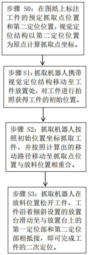
[0043] Such as figure 1 and 2 A specific implementation of the workpiece positioning method shown includes:

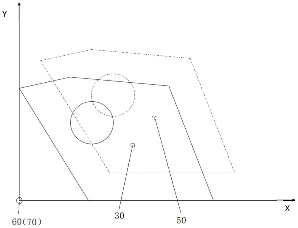
[0044] Step S0: mark the position of the predetermined grabbing point 30 and the second positioning position 70 of the workpiece on the drawing, and the visual positioning structure 20 calculates the coordinates of the grabbing point with the second positioning position 70 as the origin;

[0045] Set the first positioning position 60 on the placing table 40, when the workpiece is set on the placing table 40, the first positioning position 60 and the second positioning position 70 coincide;

[0046] Calculate the predetermined discharge position 50 coordinates of the workpiece on the placement table 40, take the first positioning position 60 as the origin, take the extension direction of the first positioning part 41 and the extension direction of the second positioning part 42 as coordinate axes to establish a coordinate system, by The coordinates of the grabbing poi...

Embodiment 2

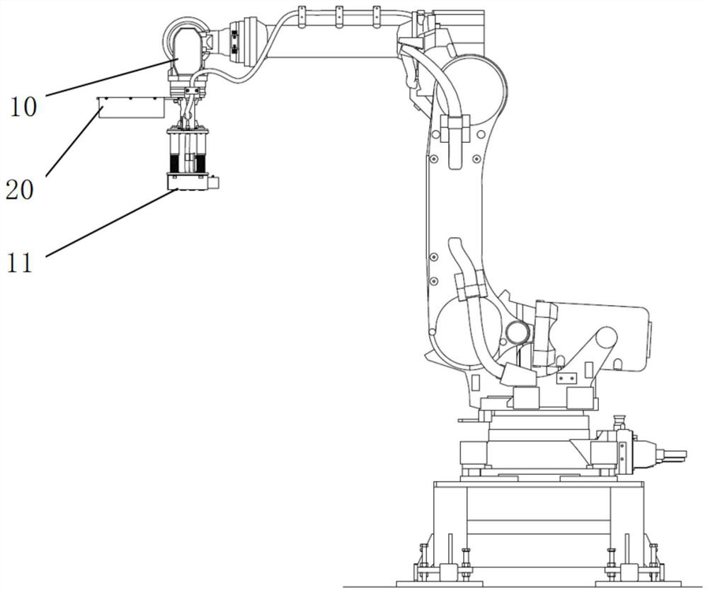
[0059] Such as image 3 and 4 A specific implementation manner of the workpiece positioning device shown includes: a grabbing robot 10 , a visual positioning structure 20 and a placement table 40 . The visual positioning structure 20 is arranged on the grasping robot 10 , and is used for identifying and locating the initial position of the workpiece and calculating the moving path of the grasping robot 10 . The placing table 40 is provided with a first positioning part 41 and a second positioning part 42 , the first positioning part 41 and the second positioning part 42 are arranged at an angle, and the placing table 40 is arranged obliquely.

[0060] The workpiece is initially positioned by setting the visual positioning structure 20, and then the first positioning part 41 and the second positioning part 42 on the placement table 40 are used for secondary positioning. Through the secondary positioning, the positioning error of the visual positioning structure 20 is eliminate...

Embodiment 3

[0069] This embodiment provides a specific implementation of the bevel cutting workstation, which includes the above-mentioned workpiece positioning device and a cutting platform. The grabbing robot 10 places the workpiece on the placement table 40 on the cutting platform according to the predetermined grabbing point 30 . The workpiece after secondary positioning is grabbed and placed on the cutting platform for cutting and processing, and the processing of the workpiece is more accurate.

[0070] To sum up, the workpiece positioning method provided in this embodiment uses the visual positioning structure to grasp the workpiece to perform preliminary positioning on the handling of the workpiece, and then places the workpiece on the placement table, using the first positioning part and the The second positioning part performs secondary positioning on the workpiece. Through the secondary positioning, the positioning error of the visual positioning structure is eliminated, and th...


PUM


Abstract

The invention provides a workpiece positioning method, a workpiece positioning device and a groove cutting workstation, and belongs to the technical field of workpiece positioning. The workpiece positioning method includes the steps that S1, a grabbing robot carries a visual positioning structure to move to a workpiece placement position, and a workpiece is photographed to obtain the initial position of the workpiece; S2, the grabbing robot grabs the workpiece at the preset grabbing point of the workpiece and moves the workpiece to a preset placing position of the workpiece on a placing table; and S3, the grabbing robot loosens the workpiece, and the workpiece slides along the obliquely-arranged placing table to abut against a first positioning part and a second positioning part on the placing table. According to the workpiece positioning method provided by the invention, the visual positioning structure is used for grabbing the workpiece so as to carry out preliminary positioning on the carried workpiece, then the workpiece is placed on the placing table, and the placing table is used for carrying out secondary positioning on the workpiece, so that the positioning errors of the visual positioning structure are eliminated. The position is made more accurate when the carrying robot takes down the workpiece from the placing table for machining, and the machining precision is guaranteed.

Description

technical field [0001] The invention relates to the technical field of workpiece positioning, in particular to a workpiece positioning method, a workpiece positioning device and a bevel cutting workstation. Background technique [0002] During the bevel cutting process, it is necessary to place the workpiece to be cut on a special cutting device for cutting. When the workpiece is placed on a special cutting device, accurate positioning is required to ensure cutting accuracy and quality. The application of vision-based industrial robots improves the intelligence level of robots, improves production efficiency, and can be used for workpiece identification and workpiece positioning. However, visual positioning is greatly affected by ambient light, and positioning accuracy is limited. Contents of the invention [0003] Therefore, the technical problem to be solved by the present invention is to overcome the defect of limited workpiece positioning accuracy in the prior art. ...

Claims


Application Information

Patent Timeline
Patent Type & Authority Applications(China)
IPC IPC(8): B25J9/16B25B11/00
CPCB25J9/1697B25J9/1664B25B11/00
Inventor 王书博封龙高
Owner 三一机器人装备(西安)有限公司
Why Eureka
Try Eureka