Beam-type pumping unit auxiliary brake device with buffering function for oil field

A technology for auxiliary brakes and pumping units, applied in mechanical equipment, drum brakes, brake actuators, etc., can solve problems such as easy slippage and accidental occurrence without protection measures, unable to guarantee automatic locking, etc., to achieve a good lock. Dead function, smooth braking, reducing the effect of dangerous situations

Active Publication Date: 2021-12-24
大庆诺源石油科技发展有限公司
View PDF11 Cites 2 Cited by
  • Summary
  • Abstract
  • Description
  • Claims
  • Application Information

AI Technical Summary

Problems solved by technology

[0005] In order to overcome the disadvantages that the auxiliary brake device cannot guarantee automatic locking, the brake device is easy to slip without protection during use, and there is no protective measure for accidents, the purpose of the present invention is to provide a kind of brake pad for oil field with increased cushioning to realize reasonable lock-up and brake protection functions. Auxiliary braking device of beam pumping unit with buffer function

Method used


Image

  • Beam-type pumping unit auxiliary brake device with buffering function for oil field
  • Beam-type pumping unit auxiliary brake device with buffering function for oil field
  • Beam-type pumping unit auxiliary brake device with buffering function for oil field

Examples


Embodiment 1

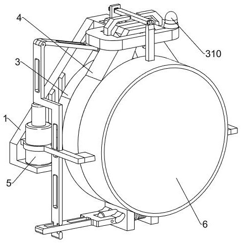
[0029] An auxiliary brake device for a beam pumping unit with a buffer function in an oil field, such as figure 1 and figure 2 As shown, it includes a mounting frame 1, a brake shaft 2, an auxiliary braking device 3, a braking device 4 and a power assembly 5. The mounting frame 1 is fixedly connected to the beam pumping unit, and the braking shaft 2 is the reducer of the beam pumping unit. One output shaft end of the brake shaft 2, the front part of the brake shaft 2 is designed in a stepped shape, and the stepped part of the brake shaft 2 is designed with threads. 3 and braking device 4 are respectively connected with the brake shaft 2 through keys, the braking device 4 is used to brake the pumping unit, and the auxiliary braking device 3 is used to cooperate with the braking of the pumping unit and the locking of the device after braking. The power assembly 5 is fixedly connected to the installation frame 1, and the power assembly 5 is respectively slidably connected with ...

Embodiment 2

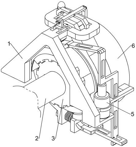
[0042] On the basis of Example 1, such as Figure 9 and Figure 10 As shown, an emergency braking device 6 is also included. The emergency braking device 6 is arranged on the front side of the brake shaft 2. The emergency braking device 6 is arranged on the mounting frame 1. The emergency braking device 6 includes a triangular claw ring 601, a second limit block 602, brake block 603, protective frame 604, second spring 605, third limit block 606 and fourth limit block 607, triangular claw ring 601 is slidably arranged on the front end of brake shaft 2, and second limit block 602 is provided with three , the three second limit blocks 602 are connected to the triangular claw ring 601 by bolts to facilitate the disassembly and reset of the emergency braking device 6, and the rear end faces of the three second limit blocks 602 are fixedly connected with brake blocks 603 and the triangular claw ring 601 respectively. The outside of the three claws is trapezoidal design, the second...


PUM


Abstract

The invention relates to the technical field of pumping unit braking, in particular to a beam-type pumping unit auxiliary brake device with a buffering function for an oil field. The beam-type pumping unit auxiliary brake device with the buffering function for the oil field increases buffering to realize reasonable locking and brake protection functions. The device comprises an auxiliary brake device, a brake device, a power assembly and the like; and the auxiliary brake device and the brake device are respectively connected with a brake shaft through keys, the power assembly is fixedly connected onto a mounting frame, and the power assembly is respectively connected with the auxiliary brake device and the brake device in a sliding manner. A pumping unit is braked through cooperation of the auxiliary brake device and the brake device, the auxiliary brake device and a buffer assembly in the brake device achieve stable braking, better locking, protection and alarm functions, the pumping unit is braked through an emergency brake device when an accident occurs, the dangerous situation caused by brake failure is avoided, and the power assembly controls the three devices in a linkage mode, and operation steps of workers are simplified.

Description

technical field [0001] The invention relates to the technical field of pumping unit braking, in particular to an auxiliary braking device for a beam pumping unit with a buffer function used in an oil field. Background technique [0002] In the process of oil extraction, the pumping unit is a very important mining equipment. Since oil extraction is mostly carried out in the wild and often faces various bad weather, ensuring the safety of the pumping unit is the key work of oil extraction. In various situations such as pumping unit overhaul, emergency stop of pumping operation, etc., the braking device of the pumping unit must be timely, accurate, reliable and safe. [0003] In the prior art, brake devices include two types of external embrace type and internal tension type, all of which utilize the friction pair to realize the braking of the pumping unit. With the increase of the service life, the normal wear and tear of the brake friction pair and the brake wheel The brakin...

Claims


Application Information

Patent Timeline
Patent Type & Authority Applications(China)
IPC IPC(8): F16D49/16F16D65/00F16D63/00F16D65/16F16D66/00F16F15/16F16D121/14F16D121/18F16D123/00F16D125/68
CPCF16D49/16F16D65/0006F16D63/00F16D65/16F16D66/00F16D2121/14F16D2121/18F16D2123/00F16D2125/68
Inventor 石磊米世超朱戈许宁张延辉赵琢萍张棣祁晨龙钱程叶静
Owner 大庆诺源石油科技发展有限公司
Why Eureka
Try Eureka