
Phased array weather radar and transmitting amplitude and phase correction method and system thereof

A weather radar and phase correction technology, applied in the field of phased array radar, can solve the problem of inability to correct the amplitude difference of the transmitting channel, and achieve the effect of eliminating the influence

Inactive Publication Date: 2021-12-24
HUNAN EASTONE WASHON TECH CO LTD
View PDF5 Cites 0 Cited by
  • Summary
  • Abstract
  • Description
  • Claims
  • Application Information

AI Technical Summary

Problems solved by technology

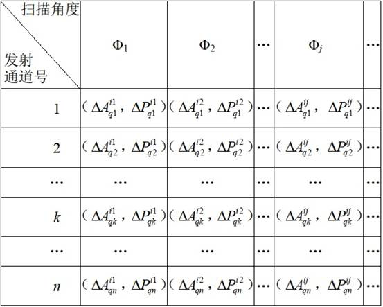
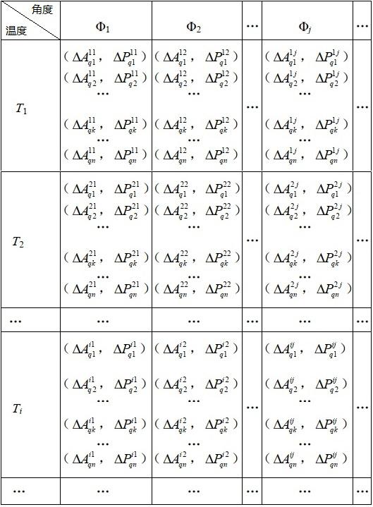
[0006] The purpose of the present invention is to provide a phased array weather radar and its transmission amplitude and phase correction method and system, to solve the problems caused by the inability to correct active standing wave changes in the prior art n The amplitude and phase difference (ie, amplitude difference and phase difference) between the transmitting channels, as well as the temperature change caused n Amplitude and phase difference between transmit channels

Method used


Image

  • Phased array weather radar and transmitting amplitude and phase correction method and system thereof
  • Phased array weather radar and transmitting amplitude and phase correction method and system thereof
  • Phased array weather radar and transmitting amplitude and phase correction method and system thereof

Examples


Embodiment 1

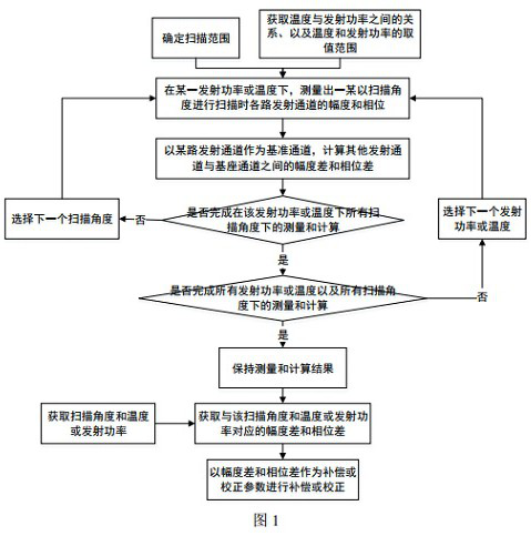
[0052] Such as figure 1 As shown, a phased array weather radar transmission amplitude and phase correction method provided in this embodiment includes the following steps:

[0053] Step 1: Determine the scanning range of the phased array weather radar according to the detection requirements and performance; and obtain the temperature of the circuit board corresponding to the transmission channel T i and transmitter transmit power Q i Correspondence between.

[0054] For phased array weather radar, there is a coupler with calibration performance between the transmission channel and the antenna. Each transmission channel couples a part of the signal through the coupler. By measuring the coupling parameters of each channel, the amplitude and phase.

[0055] The scanning range of the phased array weather radar is determined according to the detection requirements and performance. Generally, the larger the scanning range, the better. However, increasing the scanning range will...

Embodiment 2

[0086] A method for correcting the emission amplitude and phase of a phased array weather radar provided in this embodiment includes the following steps:

[0087] Step 1: Determine the scanning range of the phased array weather radar according to the detection requirements and performance; and obtain the temperature of the circuit board corresponding to the transmission channel T i and transmitter transmit power Q i Correspondence between.

[0088] In this embodiment, the scanning range is -45°~+45°, that is, -45°≤Φ j ≤+45°. In the range of -45°~+45°, n The coupling degree between the transmission channel and the main channel meets -40dB~-20dB, n The coupling amplitude consistency between the two transmission channels meets ≤0.5dB, and the phase consistency meets ≤1°.

[0089] In order to determine the influence of the transmit power of the transmitter on the temperature of the circuit board corresponding to the transmit channel, it is necessary to obtain the relationsh...


PUM


Abstract

The invention discloses a phased array weather radar and a transmitting amplitude and phase correction method and system thereof, and the method comprises the steps: measuring the amplitude and phase of each transmitting channel at different scanning angles and different transmitting powers or temperatures, and taking a certain transmitting channel as a reference channel; and calculating amplitude differences and phase differences between other transmitting channels and the reference channel, and correcting the amplitude and the phase of each transmitting channel by taking the amplitude differences and the phase differences as compensation or correction parameters. Therefore, the influence of active standing wave changes and temperature on the amplitude and the phase of each transmitting channel is reduced or eliminated.

Description

technical field [0001] The invention belongs to the technical field of phased array radar, and in particular relates to a phased array weather radar and a method and system for correcting emission amplitude and phase thereof. Background technique [0002] In the field of weather detection, phased array technology has become the main technology for the development of weather radar. The key point of phased array technology is the consistent correction of the amplitude and phase of the transmission channel. [0003] At present, phased array weather radar mainly has the following two types of methods for the consistency correction of the amplitude and phase of the transmission channel: [0004] The first category, correction methods that do not consider active influences. This method is only applicable to phased array weather radar n fixed amplitude and phase between transmit channels, although it solves the n The problem of amplitude difference and phase difference between t...

Claims


Application Information

Patent Timeline
Patent Type & Authority Applications(China)
IPC IPC(8): G01S7/40G01S13/95
CPCG01S7/40G01S13/95Y02A90/10
Inventor 王振寸怀诚杨文徐林玲胡恒林
Owner HUNAN EASTONE WASHON TECH CO LTD
Learn More