
Package carrier and manufacturing method thereof

A technology for packaging a carrier board and a manufacturing method, which is applied in the manufacture of semiconductor/solid-state devices, electrical components, and electrical solid-state devices, etc., can solve the problems of low packaging yield, poor electrical reliability, and small size, and achieves reliable structure. The effect of thinness, improved packaging yield, and good electrical conductivity

Pending Publication Date: 2021-12-24
UNIMICRON TECH CORP
View PDF0 Cites 0 Cited by
  • Summary
  • Abstract
  • Description
  • Claims
  • Application Information

AI Technical Summary

Problems solved by technology

Since the conductive blind hole has more connection interfaces, that is, there are two connection interfaces, the upper and the lower, so it is easy to cause poor conductivity.
Furthermore, conductive blind vias also have the characteristic of small contact area at the bottom of the hole. Due to the desmearing process, if the residue at the bottom of the hole cannot be effectively removed, the electrical reliability will be poor.
In addition, most of the current substrates are copper foil substrates. Due to their own material properties, irregular warping is easy to occur, which makes the coplanarity of the chip packaging area poor, and the chip cannot be effectively arranged on the copper foil substrate. In the packaging area, resulting in low packaging yield
In addition, the size of passive components is small and cannot provide a rigid support structure for the packaging area

Method used


Image

  • Package carrier and manufacturing method thereof
  • Package carrier and manufacturing method thereof
  • Package carrier and manufacturing method thereof

Examples


Embodiment Construction

[0062] Reference will now be made in detail to the exemplary embodiments of the present invention, examples of which are illustrated in the accompanying drawings. Wherever possible, the same reference numbers will be used in the drawings and description to refer to the same or like parts.

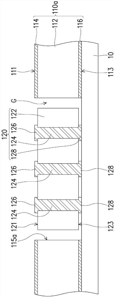
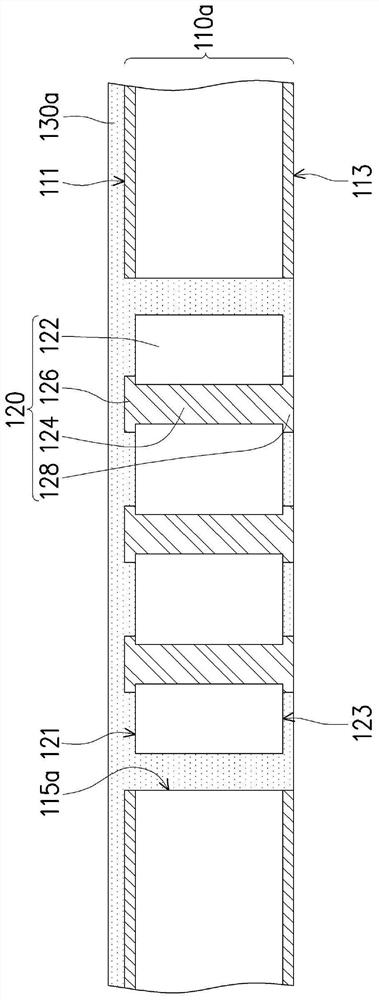
[0063] Figure 1A to Figure 1H is a schematic cross-sectional view of a manufacturing method of a package carrier according to an embodiment of the present invention. Regarding the manufacturing method of the packaging carrier of this embodiment, first, please refer to Figure 1A , providing a substrate 110a. In detail, the substrate 110a of this embodiment includes a core layer 112, a first copper foil layer 114, and a second copper foil layer 116, wherein the first copper foil layer 114 and the second copper foil layer 116 are located opposite to the core layer 112, respectively. on both surfaces. Here, the substrate 110a is, for example, a copper foil substrate, and the material of th...


PUM


Abstract

The invention provides a package carrier and a manufacturing method thereof. The package carrier includes a substrate, at least one interposer, a conductive structure layer, a first build-up structure, and a second build-up structure. The interposer is disposed in the at least one opening of the substrate, and the interposer includes a glass substrate, at least one conductive via, at least one first pad, and at least one second pad. The conductive through hole penetrates through the glass substrate, and the first connecting pad and the second connecting pad are arranged on the upper surface and the lower surface, opposite to each other, of the glass substrate respectively and connected to the two opposite ends of the conductive through hole. The conductive structure layer is arranged on the substrate and is structurally and electrically connected with the first connecting pad and the second connecting pad. The first layer-adding structure and the second layer-adding structure are respectively configured on the first surface and the second surface of the substrate and are electrically connected with the conductive structure layer. The packaging carrier plate provided by the invention has better coplanarity.

Description

technical field [0001] The invention relates to a substrate structure and a manufacturing method thereof, in particular to an encapsulation carrier board and a manufacturing method thereof. Background technique [0002] The current embedded passive element substrate (Embedded Passive Substrate, EPS) structure can only be connected on one side, and wires cannot be arranged on the back of the passive element, so it cannot be effectively used. Generally speaking, the connection between the passive components and the substrate is through conductive blind vias; or, the wiring patterns on the substrate are directly connected to the contacts of the passive components for single-sided wiring layout. Since the conductive blind via has more connection interfaces, that is, there are upper and lower connection interfaces, it is easy to cause poor conductivity. Furthermore, conductive blind vias also have the characteristic of small contact area at the bottom of the hole. Since the desm...

Claims


Application Information

Patent Timeline
Patent Type & Authority Applications(China)
IPC IPC(8): H01L23/498H01L21/48
CPCH01L23/49838H01L23/49811H01L23/49827H01L21/4853H01L21/486
Inventor 林纬廸简俊贤陈裕华
Owner UNIMICRON TECH CORP
Learn More