An automatic feeding device for a spraying machine

An automatic feeding and spraying machine technology, applied in the direction of spraying devices, conveyors, conveyor objects, etc., can solve problems such as inability to realize accurate feeding and transportation, inability to unload force buffering of products, damage to spraying parts, etc., to increase the spraying effect , energy consumption balance, quality improvement effect

Active Publication Date: 2022-03-29
中铁一局集团电务工程有限公司
View PDF9 Cites 0 Cited by
  • Summary
  • Abstract
  • Description
  • Claims
  • Application Information

AI Technical Summary

Problems solved by technology

[0005] This application provides an automatic feeding device for a spraying machine, which solves the problem that the spraying machine in the prior art cannot unload and buffer the product when loading the material. The product will rush into the spraying part due to inertia and cause damage, and multiple products are easy to be placed on the screen. The technical problems of collisions on the conveyor belt and the inability to realize accurate feeding and transportation have realized the power-assisted buffering of the loaded products to avoid damage caused by inertial forces, and can ensure that the feeding rate is consistent with the spraying workmanship. At the same time, it can accurately The purpose of transporting the product to the painted part efficiently

Method used


Image

  • An automatic feeding device for a spraying machine
  • An automatic feeding device for a spraying machine
  • An automatic feeding device for a spraying machine

Examples


Embodiment Construction

[0027] The following will clearly and completely describe the technical solutions in the embodiments of the present invention with reference to the accompanying drawings in the embodiments of the present invention. Obviously, the described embodiments are part of the embodiments of the present invention, not all of them. Based on the embodiments of the present invention, all other embodiments obtained by persons of ordinary skill in the art without making creative efforts belong to the protection scope of the present invention.

[0028] In the description of the embodiments of the present invention, it should be noted that the terms "center", "upper", "lower", "left", "right", "vertical", "horizontal", "inner", "outer " and other indicated orientations or positional relationships are based on the orientations or positional relationships shown in the drawings, and are only for the convenience of describing the embodiments of the present invention and simplifying the description,...


PUM


Abstract

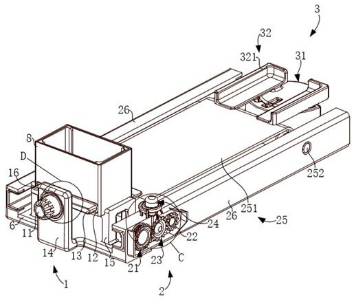
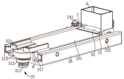
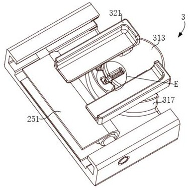
The application discloses an automatic feeding device for a spraying machine, which includes a feeding speed control mechanism, a stop assisting buffer mechanism and a material transport corner mechanism; the feeding speed control mechanism includes a pushing part and a feeding table; the stop assisting buffer mechanism includes a driving gear assembly, driven gear, transition gear assembly, lifting assembly and conveyor belt assembly; both the driving gear assembly and the driven gear are meshed with the transition gear assembly; the lifting assembly can drive the transition gear assembly to perform lifting actions; the transport angle mechanism includes a rotating assembly and receiving table. This application solves the technical problems in the prior art that the spraying machine cannot unload the product when loading materials, the product is easily damaged due to inertia rushing into the spraying part, and multiple products are easy to accumulate on the conveyor belt. The loaded product is assisted and buffered to avoid damage due to inertial force, to ensure that the feeding rate is consistent with the spraying process, and to accurately deliver the product to the purpose of the sprayed part.

Description

technical field [0001] The present application relates to the technical field of spraying machine equipment, in particular to an automatic feeding device for a spraying machine. Background technique [0002] Spraying machine is a special coating equipment using spraying technology. The principle is to control the air flow to instantly push the air distribution reversing device to change direction, so that the piston of the air motor makes a stable and continuous reciprocating motion, pressurizes the inhaled paint, and passes through the high-pressure soft The tube transports the paint to the spray gun of the spraying machine, and the spray gun atomizes the paint instantly and releases it to the surface of the object to be coated. The spraying machine is mainly composed of a feeding device, a spray gun, and an atomization source. It is suitable for metal decorative surfaces and steel corrosion protection. , automobile manufacturing and other industries. [0003] Such as Chin...

Claims


Application Information

Patent Timeline
Patent Type & Authority Patents(China)
IPC IPC(8): B05B13/02B65G47/82B65G47/74B65G47/244B65G23/04B65G47/22
CPCB05B13/0235B65G47/82B65G47/74B65G47/244B65G23/04B65G47/22
Inventor 骆晓何健刘稳宋旭刚陆升郭新伟杜银龙刘国彦赵甲骆翔翔崔凯
Owner 中铁一局集团电务工程有限公司
Why Eureka
Try Eureka