
Automatic feeding equipment for laser cutting of sheet metal parts

A technology of laser cutting and automatic feeding, which is applied in laser welding equipment, metal processing equipment, welding equipment, etc., can solve the problem of not being able to adjust the position of the suction cup flexibly, and achieve the effect of flexible adjustment of the position of the suction cup and easy gathering

Inactive Publication Date: 2021-12-28
苏州宽窄机械设备有限公司
View PDF0 Cites 0 Cited by
  • Summary
  • Abstract
  • Description
  • Claims
  • Application Information

AI Technical Summary

Problems solved by technology

[0003] The purpose of the present invention is to provide an automatic feeding equipment for laser cutting of sheet metal parts to solve the problem that the above background technology does not have the function of flexibly adjusting the position of the suction cup to adapt to the size of the sheet metal

Method used


Image

  • Automatic feeding equipment for laser cutting of sheet metal parts
  • Automatic feeding equipment for laser cutting of sheet metal parts
  • Automatic feeding equipment for laser cutting of sheet metal parts

Examples


Embodiment 1

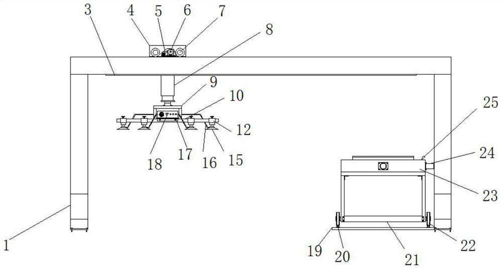
[0027] Example 1: See Figure 1-6 , an automatic feeding equipment for laser cutting of sheet metal parts, comprising a gantry 1, a housing 4 is arranged above the gantry 1, a first hydraulic cylinder 8 is fixedly connected to the bottom of the housing 4, and the first hydraulic cylinder 8 The bottom end is fixedly connected with a fixed frame 9, and the front and rear ends of the fixed frame 9 are welded horizontally with a horizontal frame 10 respectively. There is a bottom plate 19, a frame 21 is arranged on the top of the bottom plate 19, and the top of the frame 21 is fixedly connected with a cover 23; The wheel groove 2, the rear end of the inner bottom of the housing 4 is equipped with a gear box 5, the bottom of the inner housing 4 is fixedly connected with a servo motor 6, the two sides of the front and rear ends of the housing 4 are respectively movably connected with rollers 7, and the top of the bottom plate 19 Slide rails 20 are installed on both sides of the fra...

Embodiment 2

[0031] Embodiment 2: a vacuum pump 18 is installed on the top of the mounting plate 17, and a trachea 16 is arranged between one side of the suction cup 15 and one side of the vacuum pump 18, so that the vacuum pump 18 can vacuum the air in the suction cup 15;

[0032] Specifically, such as figure 1 and Figure 5 As shown, then the first hydraulic cylinder 8 is pushed down, the suction cup 15 is close to the sheet material, the vacuum air pump 18 on the mounting plate 17 is started, and the air in the suction cup 15 is sucked away, and under the action of air pressure, the suction cup 15 will suck up the sheet material , and through the displacement of the upper driving mechanism, the sheet material is transported to the cutting platform, which realizes the function of conveniently sucking up the sheet material for transfer.

Embodiment 3

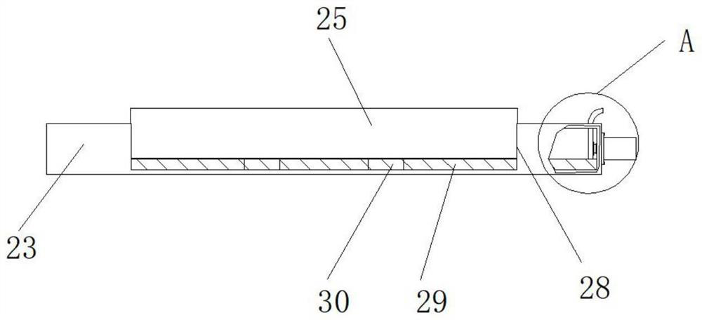
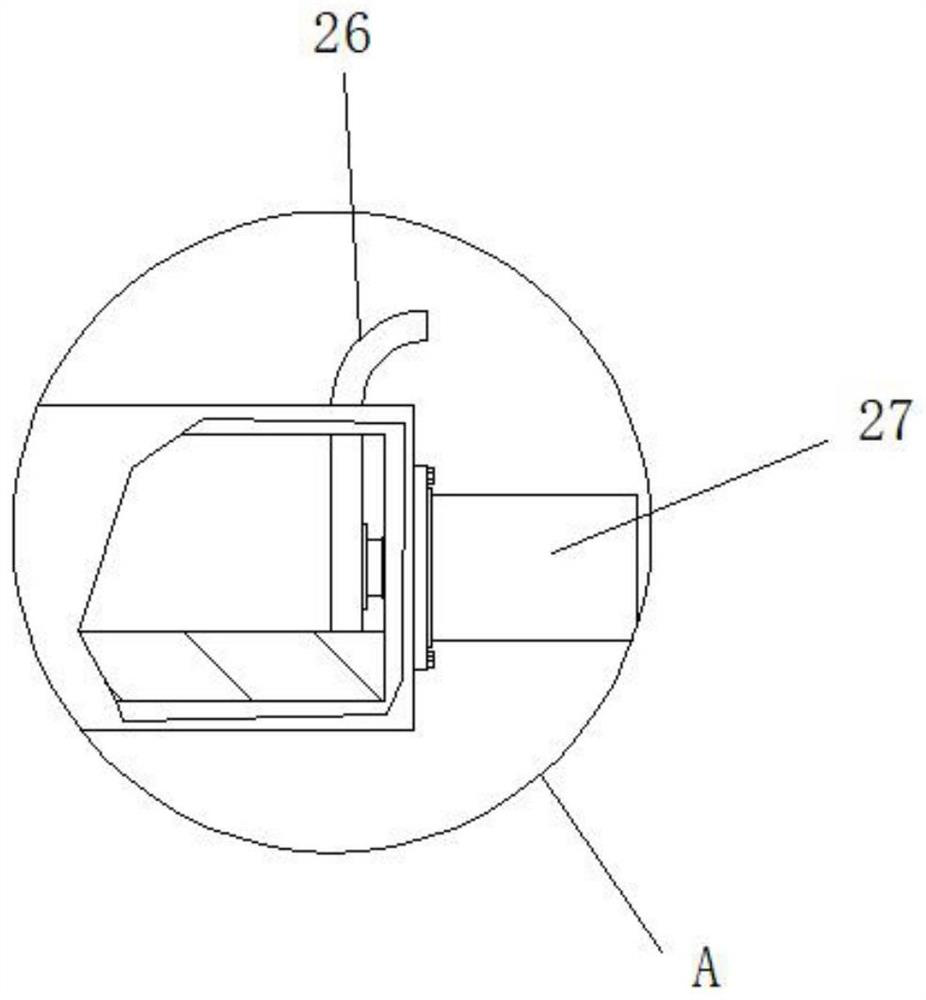
[0033] Embodiment 3: One side inside the casing 23 is provided with a first arcuate pushing plate 25, the front end inside the casing 23 is provided with a second arcuate pushing plate 26, the first arcuate pushing plate 25, the second arcuate pushing plate The top of the board 26 has a certain radian, which is convenient to gather the boards together to prevent overhead;

[0034] Specifically, such as figure 2 and image 3As shown, the forklift forks up the stacked sheets and places them in the casing 23. The radians at the top of the first arcuate push plate 25 and the second arcuate push plate 26 can make the sheets slide down to the bottom of the casing 23 quickly, preventing Occurrence sheet material tilts overhead, causes suction cup 15 to be unable to pick up, has realized the function that prevents sheet material from tilting overhead.


PUM


Abstract

The invention discloses automatic feeding equipment for laser cutting of sheet metal parts. The automatic feeding equipment comprises a portal frame, a shell is arranged above the portal frame, a first hydraulic air cylinder is fixedly connected to the bottom end of the shell, a fixing frame is fixedly connected to the bottom end of the first hydraulic air cylinder, transverse frames are transversely welded to the front end and the rear end of the fixing frame correspondingly, and a feeding width adjusting mechanism is arranged at the top ends of the transverse frames. According to the automatic feeding equipment for laser cutting of the sheet metal parts, limiting holes, square sleeves, adjusting hand wheels, fixing rods, suction cups, air pipes, a mounting plate and a vacuum air pump are arranged, when the automatic feeding equipment is used, according to the size and the width of a sheet metal, the adjusting hand wheels are unscrewed firstly, then the square sleeves slide, the suction cups are evenly distributed above sheet metal, then the adjusting hand wheels are screwed, the adjusting hand wheels are clamped into limiting holes to complete fixing, the function of flexibly adjusting the positions of the suction cups to adapt to the size of the sheet metal is achieved, and the problem that the device does not have the function of flexibly adjusting the positions of the suction cups to adapt to the size of the sheet metal is solved.

Description

technical field [0001] The invention relates to the technical field of automatic feeding equipment, in particular to an automatic feeding equipment for laser cutting of sheet metal parts. Background technique [0002] With the continuous improvement of cutting equipment, laser cutting has become one of the main methods of sheet metal processing. However, laser cutting equipment is troublesome to load and needs to be loaded manually or through automatic feeding equipment. The current market Most of the more common laser cutting automatic feeding equipment for sheet metal parts in the world are fed by vacuum suction cups. The structure is simple, and there are some problems in the use process that need to be improved. For example, the position of the suction cup is fixed, and it cannot be flexibly adjusted according to the size of the sheet. The position of the suction cup, and secondly, during the feeding process, due to the uneven position of the sheet material, it is easy t...

Claims


Application Information

Patent Timeline
Patent Type & Authority Applications(China)
IPC IPC(8): B23K26/70B23K26/38
CPCB23K26/702B23K26/38
Inventor 张碧玉陈仁浩
Owner 苏州宽窄机械设备有限公司
Learn More