
Coal sample pneumatic transmission system based on pipeline transfer

A coal sample, pneumatic transmission technology, applied in the direction of conveyors, conveyor objects, transportation and packaging, etc., can solve the problems of dirty coal sample bottles, movement restrictions of the transmission frame, easy to block, etc.

Active Publication Date: 2022-05-27
淮北矿业股份有限公司涡北选煤厂 +1
View PDF0 Cites 0 Cited by
  • Summary
  • Abstract
  • Description
  • Claims
  • Application Information

AI Technical Summary

Problems solved by technology

[0003] In the prior art, an annular blade is usually connected to the outer wall of the transmission frame, so that during the transmission movement of the transmission frame inside the transmission pipe, the blade is used to clean the stubborn stains on the inner wall of the transmission pipe. The combination is tighter, and the resistance of the blade when removing stains is relatively large, which limits the movement of the transmission frame inside the transmission pipe and is prone to blockage; the cleaned stains spread around under the action of the air flow inside the transmission pipe, It is easy to cause the transmission frame and the coal sample bottle inside the transmission frame to be dirty, and the combination of the cleaned stains and the condensed water droplets inside the transmission pipe will easily cause the cleaned stains to adhere to the inner wall of the transmission pipe again, making it difficult to clean the stains Due to temperature changes, air compression and other reasons, condensation water will appear on the inner wall of the pneumatic transmission pipeline. In addition, the transmission pipeline is not sealed tightly, rainwater leakage and sample bottles may cause moisture inside the transmission pipeline. The wetness of the inner wall of the pipeline makes the cleaned stains mixed with water droplets to form a paste, which hinders the transmission of the transmission frame inside the transmission pipeline; the transmission frame carries coal sample bottles for transmission inside the transmission pipeline , after being transported to the position of the workstation, it falls vertically under the action of the propelling airflow and collides with one end of the transmission pipe. and shortened service life of the transmission frame;

Method used


Image

  • Coal sample pneumatic transmission system based on pipeline transfer
  • Coal sample pneumatic transmission system based on pipeline transfer
  • Coal sample pneumatic transmission system based on pipeline transfer

Examples


Embodiment 1

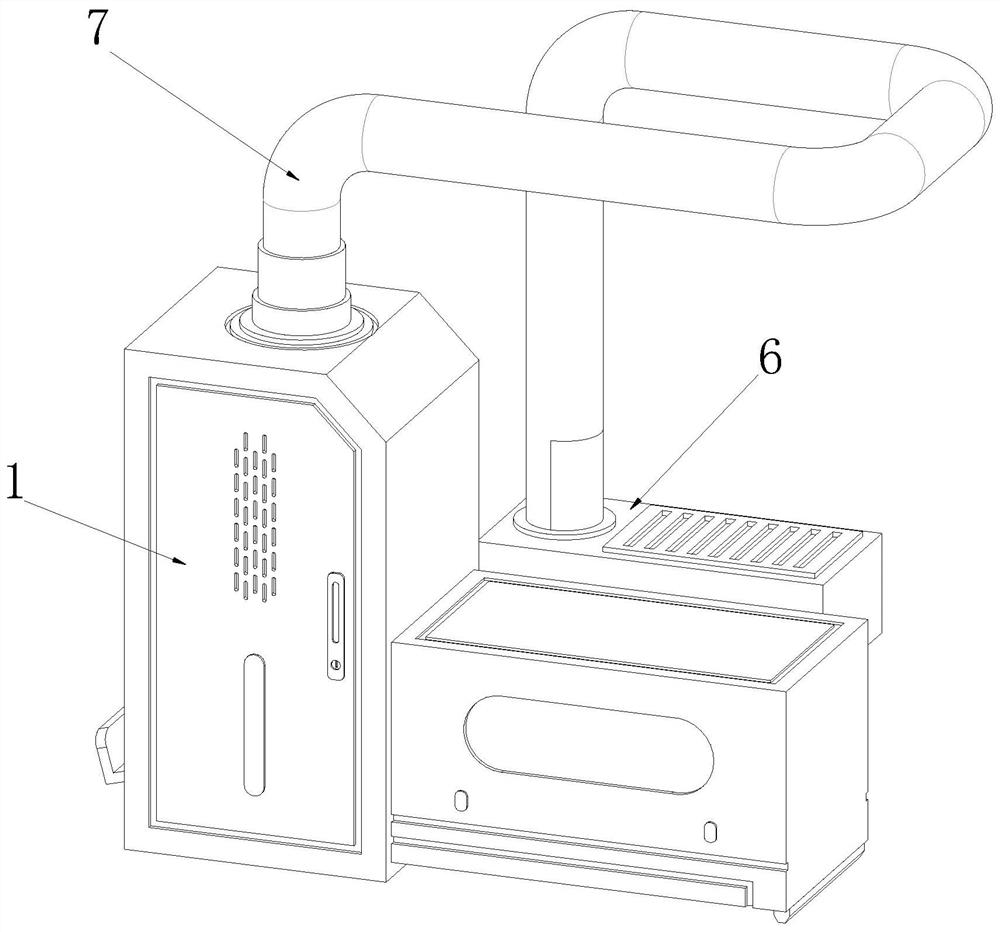
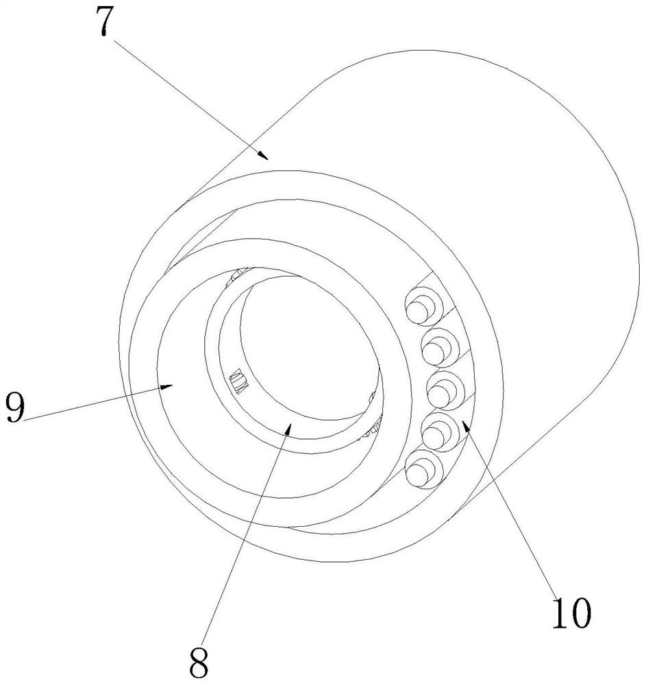
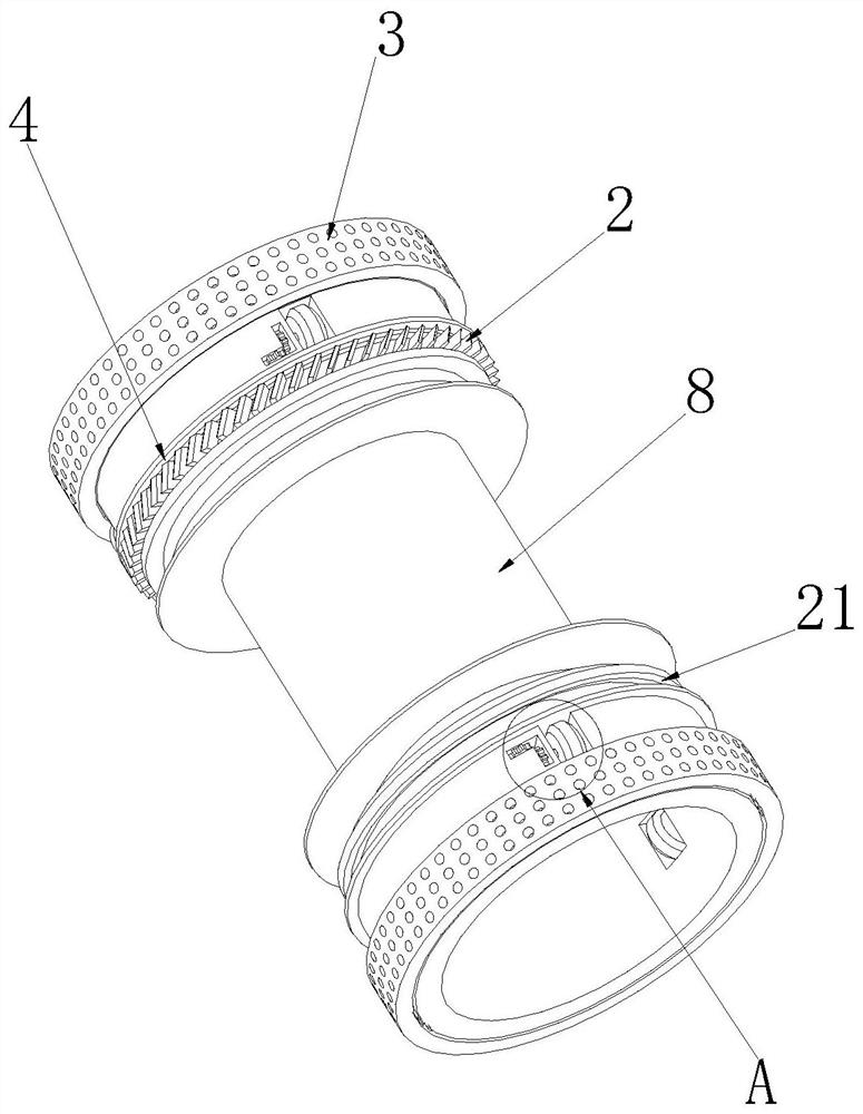
[0040] see Figure 1-5 As shown, the coal sample pneumatic transmission system based on pipeline transfer includes a sample storage workstation 1, a sampling workstation 6, a protective pipeline 7, a transmission frame 8, a transmission pipeline 9 and a communication control cable 10. The upper surface of the sample storage workstation 1 is connected with a The protective pipeline 7, one end of the protective pipeline 7 away from the sample storage workstation 1 is connected with the sampling workstation 6, the inner side wall of the protective pipeline 7 is provided with a transmission pipeline 9, and the inner side wall of the protective pipeline 7 is provided with a communication control cable 10 on the side close to the transmission pipeline 9. The inner wall of the pipeline 9 is provided with a transmission frame 8;

[0041] The power fan connected inside the sample storage station 1 at the position corresponding to the transmission pipe 9 can give the coal sample bottle ...

Embodiment 2

[0046] see Figure 8-9 As shown, the outer side wall of the transmission frame 8 is provided with a miscellaneous conveying mechanism 4 on both sides close to the miscellaneous blade 22, and the miscellaneous conveying mechanism 4 includes a miscellaneous storage box 45. The plate 43, the outer side walls of the second baffle 43 and the first baffle 41 are all in close contact with the inner wall of the transmission pipe 9, so that the first baffle 41, the outer side wall of the transmission frame 8, the second baffle 43 and The four inner walls of the transmission pipe 9 can form a closed annular space, so that the impurities cleaned by the cleaning blade 22 inside the annular space are not easy to spread around, causing the transmission pipe 9, the transmission frame 8 and the coal sample bottle to be dirty. The outer side wall of the plate 43 is provided with a miscellaneous guide hole 44 at the position corresponding to the miscellaneous storage box 45. The side of the out...

Embodiment 3

[0050] see Figure 6-7 As shown, a wiping mechanism 3 is provided on the outer side of the outer side wall of the transmission frame 8. The wiping mechanism 3 includes a second rotating groove 31. The inner side wall of the second rotating groove 31 is slidably connected with a second rotating ring 33. The shape of the second rotating groove 31 is inverted. T-shaped, the shape of the second rotating ring 33 is an I-shaped, and the width of the second rotating ring 33 is larger than the width of the outer opening of the second rotating groove 31, so that the second rotating ring 33 is not easily connected with the second rotating groove 31. In the case of mutual separation, the outer side wall of the second rotating ring 33 is connected with a water-absorbing sponge 32, and the thickness of the water-absorbing sponge 32 is larger than the distance between the transmission frame 8 and the transmission pipe 9, so that the water-absorbing sponge 32 is squeezed inside the transmissi...


PUM


Abstract

The invention relates to pipeline pneumatic transmission technology, which is used to solve the problem that the pneumatic transmission pipeline is affected by stubborn stains and water vapor on the inner wall during the transmission process, making normal transmission difficult and collision damage at the end of transmission, specifically a coal sample pneumatic transmission system based on pipeline transfer , including a sample storage workstation, a sampling workstation, a protective pipeline, a transmission frame, and a transmission pipeline; the present invention cleans stubborn stains on the inner wall of the transmission pipeline through several cleaning blades distributed obliquely on the first rotating ring, and the cleaning blades The hindering force between the stubborn stains and the moving direction of the transmission frame is reduced, and the ring-shaped airtight space formed prevents the spread of debris under cleaning, and the water-absorbing sponge is used to prevent condensation on the inner wall of the transmission pipe during the transmission process. The absorbing force is buffered by the spring, and the force of the falling collision is buffered. During the buffering process, the inertial force of the rotation of the second rotating ring is used to squeeze out the moisture inside the absorbent sponge.

Description

technical field [0001] The invention relates to a pipeline pneumatic transmission technology, in particular to a coal sample pneumatic transmission system based on pipeline transfer. Background technique [0002] The pneumatic pipeline logistics transmission system consists of air compressors, pipelines, pipeline commutators, etc. The basic purpose is to convey goods. The working principle is that the air compressor extracts and compresses air as power, and automatically pushes the goods to move in a closed pipeline; [0003] In the prior art, a ring-shaped blade is usually connected to the outer side wall of the transmission frame, so that the blade is used to clean the stubborn stains on the inner wall of the transmission pipe during the transmission and movement of the transmission frame inside the transmission pipe. The combination is tighter, and the resistance of the blade when removing stains is greater, which restricts the movement of the transmission frame inside th...

Claims


Application Information

Patent Timeline
Patent Type & Authority Patents(China)
IPC IPC(8): B65G51/04B65G51/18B65G45/14B65G45/10B65G51/26
CPCB65G51/04B65G51/18B65G45/14B65G45/10B65G51/26
Inventor 薛峰代佩黄海峰江渭清欧战备王宇
Owner 淮北矿业股份有限公司涡北选煤厂
Learn More