
Rotating vane type steering engine motor

A technology of rotary vane and steering gear, which is applied in the direction of electromechanical devices, mechanical equipment, and control of mechanical energy, can solve the problems of reduced sealing and working life, low sealing and life of steering gear, and increased difficulty in processing and assembly. Optimized mechanical seal, simple structure, improved reliability and fault tolerance

Pending Publication Date: 2021-12-28
BEIJING JOINTECH ELECTRO HYDRAULIC
View PDF6 Cites 0 Cited by
  • Summary
  • Abstract
  • Description
  • Claims
  • Application Information

AI Technical Summary

Problems solved by technology

When manufacturing this type of rotary vane motor, it is Shaped seals require cumbersome assembly procedures during installation, which increases the difficulty of processing and assembly in the production process and affects production efficiency
At the same time, the existing rotary vane steering gear motor also has the following defects: 1) when all the blades are in use, the system noise is relatively high, and when a certain blade dynamic seal fails or fails, the entire steering gear cannot work; 2) the existing The airtightness and service life of the steering gear are relatively low. The maximum working pressure of the domestic rotary vane steering gear motor is about 10MPa. The end of the moving blade is provided with a seal, and there are two 90° knuckles in this dynamic sealing structure, which reduces its sealing performance and working life; at the same time The two ends of the dynamic seal move up under the pressure of the oil pressure, resulting in increased leakage. The above reasons lead to the current maximum working pressure of the rectangular blade rotary vane steering gear motor can only reach about 10MPa

Method used


Image

  • Rotating vane type steering engine motor
  • Rotating vane type steering engine motor
  • Rotating vane type steering engine motor

Examples


Embodiment Construction

[0029] The concepts, specific structures, and technical effects of the present invention will be described below in conjunction with the examples and drawings to fully understand the objects, programs and effects of the present invention. It should be noted that the features of the present application and the features in the embodiments in the present application can be combined with each other in the case of an unable conflict.

[0030] It should be noted that if there is no special instruction, when a feature is called "fixed", "connection" in another feature, it can be directly fixed, connected in another feature, can also be indirectly fixed, connected in another One feature. Furthermore, the above, lower, left, right, and bottom, etc., which are used in the present invention are merely the interposedation of each of the components of the invention in the drawings.

[0031] Moreover, unless otherwise defined, all techniques and scientific terms used herein are the same as thos...


PUM


Abstract

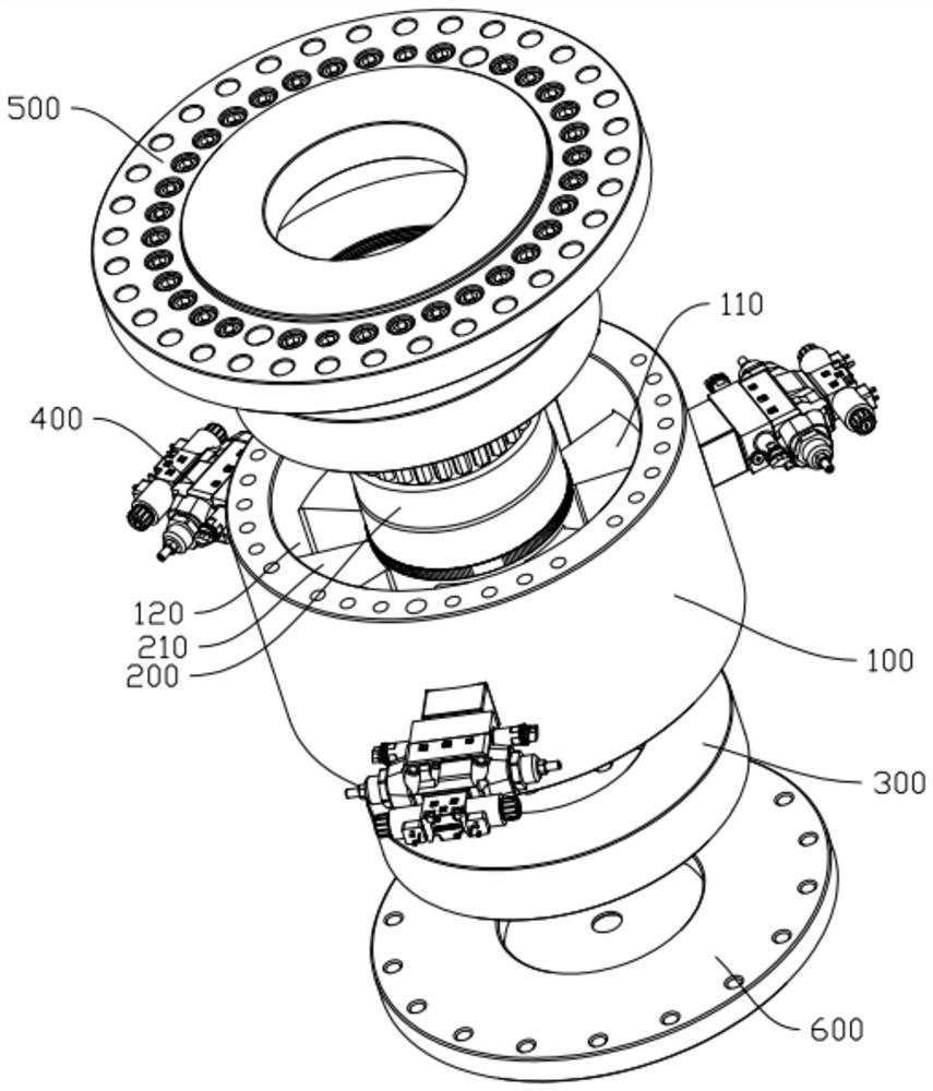
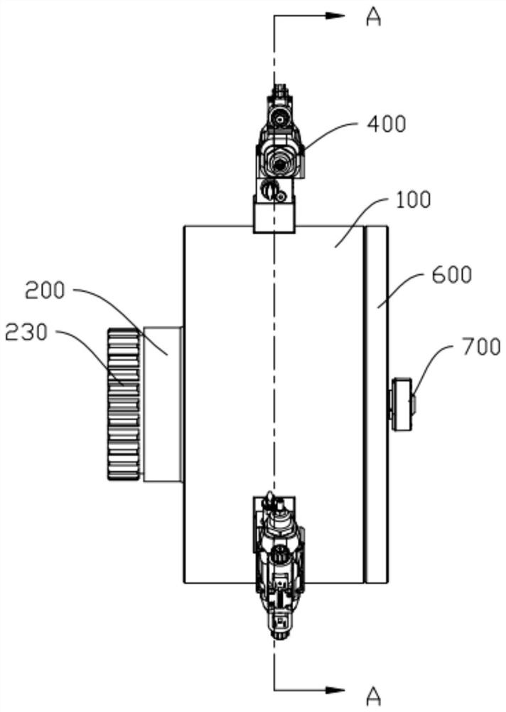
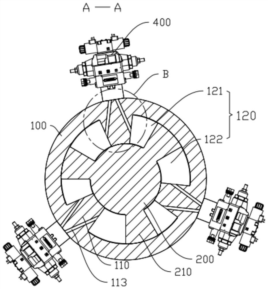
The embodiment of the invention discloses a rotating vane type steering engine motor which comprises a shell, a rotor and end covers, wherein the interior of the shell is hollow, a plurality of fixed vanes are arranged on the inner wall of the shell, a rotating gap is formed between every two adjacent fixed vanes, and a first curved surface matched with the surface of the rotor in shape is arranged at the end of each fixed vane; the plurality of first curved surfaces are matched to form a rotating hole in the shell; moving blades are arranged on the outer wall of the rotor, and the rotor is rotatably inserted into the rotating hole, so that the moving blades can swing in the rotating gap; the two end covers are embedded in the shell, and the two ends of the rotor are sleeved with the two end covers respectively; the rotor is in clearance fit with the rotating hole, the moving blades are in clearance fit with the inner wall of the shell, the end covers are in interference fit with the inner wall of the shell, and the end covers are in clearance fit with the rotor. By omitting the mounting of a sealing element, the difficulty can be greatly reduced during actual processing and assembling, and the overall production efficiency is improved.

Description

Technical field [0001] The present invention relates to a turret motor, belonging to the technical field of transmission. Background technique [0002] The sealing form of the existing turret can generally use the dynamic sealing structure, that is, the seal is provided in the movable blade, thereby avoiding a severe leakage in the process of the turret motor during operation. When manufacturing this type of turn-leaved motor is produced Shaped seals require cumbersome assembly steps in installation, increase processing and assembly difficulty during production, affecting production efficiency. At the same time, the existing turret motor also has the following defects: 1) The system noise is high when all blades are used, and when a blade is moving seal, the entire steering machine cannot work; 2) Existing The steering gear is low, and the highest working pressure of the domestic turm steering gear motor is about 10 MPa. This is because the shape of the steering gear motor leave...

Claims


Application Information

Patent Timeline
Patent Type & Authority Applications(China)
IPC IPC(8): F15B15/12F15B15/20F15B15/28F16J15/16F16J15/54H02K5/04H02K5/10H02K7/10
CPCF15B15/12F15B15/202F15B15/2838F16J15/16F16J15/54H02K5/04H02K5/10H02K7/10
Inventor 向超胡科郭世杰刘建文
Owner BEIJING JOINTECH ELECTRO HYDRAULIC
Learn More