Surgical tool driving transmission system based on planar motion mechanism and surgical robot

A technology for driving a transmission system and a plane motion mechanism, applied in the field of surgical robots, can solve problems such as complex structure, and achieve the effects of simple principle, easy implementation and high reliability

Pending Publication Date: 2021-12-31
BEIJING SURGERII TECH CO LTD
View PDF0 Cites 0 Cited by
  • Summary
  • Abstract
  • Description
  • Claims
  • Application Information

AI Technical Summary

Problems solved by technology

[0004] The existing continuum structure generally directly pushes and pulls the driving wire in the continuum structure through the driving mechanism, so as to realize the bending of the continuum structure in any direction. High performance, good stability and other more stringent requirements, the existing drive structure has gradually been unable to meet the above requirements, and the existing drive method is to directly push and pull the drive wire to move, so when the number of drive wires is large, the drive mechanism The number of will increase accordingly, making the structure complex

Method used


Image

  • Surgical tool driving transmission system based on planar motion mechanism and surgical robot
  • Surgical tool driving transmission system based on planar motion mechanism and surgical robot
  • Surgical tool driving transmission system based on planar motion mechanism and surgical robot

Examples


Embodiment 1

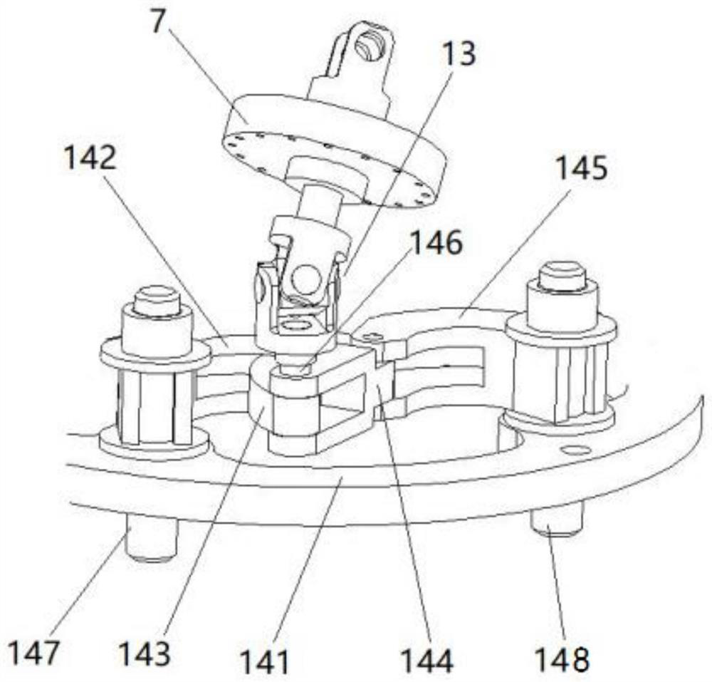
[0043] In this example, if Figure 4 As shown, the driving connection part 13 adopts a double-joint universal joint, which is mainly composed of a first universal joint 131 and a second universal joint 132 connected in series, and the far end and the proximal end of the first universal joint 131 The base plate 4 is connected, the proximal end of the first universal joint 131 is connected with the distal end of the second universal joint 132, and the proximal end of the second universal joint 132 passes through the proximal stop disc 7 and is connected with the proximal stop disc 7 , the part of the second universal joint 132 located on the proximal side of the proximal stop disc 7 forms a free end. At this time, the six connection nodes can be combined as follows: the first connection node uses a fixed connection, the second connection node uses a universal joint, the third connection node uses a cylindrical pair connection, the fourth connection node uses a universal joint, a...

Embodiment 2

[0047] In this example, if Image 6As shown, the driving connection part 13 adopts a double-joint ball joint, which is mainly composed of a first ball joint 133 and a second ball joint 134 connected in series, and the distal end and the proximal end of the first ball joint 133 The base plate 4 is connected, the proximal end of the first ball joint 133 is connected with the distal end of the second ball joint 134 through a universal coupling, and the proximal end of the second ball joint 134 passes through the proximal stop disc 7 and is connected with the The proximal stop disc 7 is connected, and the part of the second ball joint 134 located on the proximal side of the proximal stop disc 7 forms a free end. At this time, the six connection nodes can be combined as follows: the first connection node uses a fixed connection, the second connection node uses a spherical joint, the third connection node uses a cylindrical pair connection, the fourth connection node uses a spherica...

Embodiment 3

[0051] In this example, if Figure 7 As shown, the driving connection part 13 adopts a four-bar hinge joint 135, which is mainly composed of a first link A, a second link B, a third link C, and a fourth link D in series. , the distal end of the first link A is connected to the proximal base plate 4, the proximal end of the first link A is hinged to the distal end of the second link B, and the proximal end of the second link B is connected to the third link C The distal end of the cylinder pair is connected, the proximal end of the third connecting rod C is hinged with the distal end of the fourth connecting rod D, and the proximal end of the fourth connecting rod D passes through the proximal stop disc 7 and is connected with the proximal stop disc 7, The part of the fourth connecting rod D located on the proximal side of the proximal stop disc 7 forms a free end. At this time, the following combination of six connection nodes is taken as an example: the first connection node...


PUM


Abstract

The invention relates to a surgical tool driving transmission system based on a planar motion mechanism and a surgical robot. The surgical tool driving transmission system comprises a flexible continuous body and a driving mechanism, wherein the flexible continuous body comprises a near-end continuous body which comprises a near-end basal disc, a near-end stop disc and a plurality of structural bone; a far-end continuous body which comprises a far-end basal disc and a far-end stop disc; and a driving connecting part, wherein the far end of the driving connecting part is connected with the near-end basal disc, the near end of the driving connecting part penetrates through the near-end stop disc and is connected with the near-end stop disc, and the part, located at the near-end side of the near-end stop disc, of the driving connecting part forms a free end; near ends of the structural bones are fixedly connected with the near-end stop disc, and far ends of the structural bones sequentially penetrate through the near-end basal disc and the far-end basal disc and are fixedly connected with the far-end stop disc; and the driving mechanism is connected with the free end of the driving connecting part. According to the surgical tool driving transmission system based on the planar motion mechanism and the surgical robot, driving wires of the flexible continuous body can be prevented from being directly pushed and pulled, the driving of a large number of driving wires can be not limited by the number of driving mechanisms, and meanwhile, the surgical tool driving transmission system is compact in structure, simple in principle, easy to implement and very high in reliability and flexibility.

Description

technical field [0001] The invention relates to a driving transmission device, in particular to a driving transmission system of a surgical tool based on a planar motion mechanism and a surgical robot including the driving transmission system of the surgical tool. Background technique [0002] Minimally invasive surgery has less trauma to patients and higher postoperative output, and has occupied an important position in surgical operations. Minimally invasive surgery uses surgical tools and surgical instruments including visual lighting modules and surgical manipulation arms to enter the human body through incisions or natural orifices to reach the surgical site for surgery. The distal structure of the existing surgical instrument is mainly a series hinge of multiple rods, which is driven by the tension of the wire rope, so that the surgical instrument can be turned at the hinged joint. Since the wire rope must be kept in a continuous tension state through the pulley, it i...

Claims


Application Information

Patent Timeline
IPC IPC(8): A61B17/00A61B34/30F16H21/12F16H21/34
CPCA61B17/00234A61B34/30A61B34/70F16H21/12F16H21/34A61B2017/00367A61B2034/301
Inventor 徐凯刘旭
Owner BEIJING SURGERII TECH CO LTD
Why Eureka
Try Eureka