Surgical tool driving system and surgical robot

A surgical tool and drive system technology, which is applied in the field of surgical tool drive system and surgical robot, can solve the problems of complex structure and failure to meet the requirements of drive mode, and achieve the effect of simple principle, high reliability and flexibility, and compact structure

Pending Publication Date: 2021-12-31
BEIJING SURGERII TECH CO LTD
View PDF0 Cites 2 Cited by
  • Summary
  • Abstract
  • Description
  • Claims
  • Application Information

AI Technical Summary

Problems solved by technology

[0004] The existing continuum structure generally directly pushes and pulls the driving wire in the continuum structure through the driving mechanism, so as to realize the bending of the continuum structure in any direction. High performance, good stability and other stricter requirements, the existing drive transmission structure has gradually been unable to meet the requirements of the existing drive mode, and the existing drive mode is to directly push and pull the drive wire to move, so when the number of drive wire When more, the number of driving mechanisms will increase accordingly, making the structure complex

Method used


Image

  • Surgical tool driving system and surgical robot
  • Surgical tool driving system and surgical robot
  • Surgical tool driving system and surgical robot

Examples


Embodiment approach

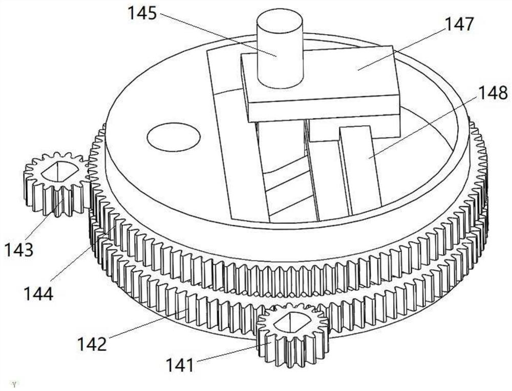
[0083] According to one embodiment of the present invention, as shown in the figure, the gear chute mechanism includes: a first driving gear 141, a first driven gear 142, a second driving gear 143, a second driven gear 144, a sliding pin 145, Connecting rod 146, slide block 147. The first driven gear 142 and the second driven gear 144 are arranged coaxially, and both can rotate relative to each other. The first driving gear 141 meshes with the first driven gear 142 . One end of the connecting rod 146 is provided with a first sliding slot 1461 , and the outer peripheral surface 1462 of the other end is tooth-shaped for meshing with the teeth of the inner ring of the first driven gear 142 . The rotating shaft 149 fixedly connected with the connecting rod 146 moves through the eccentric position of the second driven gear 144 . The second driven gear 144 is provided with a second chute 1441 along the center line of the diameter of the disk surface, and a slide rail 148 parallel ...


PUM


Abstract

The invention relates to a surgical tool driving system and a surgical robot. The driving system comprises a flexible continuous body structure and a driving transmission mechanism, wherein the flexible continuous body structure comprises a near-end continuous body 1, a first structural bone 13, a second structural bone 12 and a far-end continuous body 3; and the driving transmission mechanism 14 comprises: a rotating mechanism which comprises a first rotatable part and a second rotatable part, wherein the rotating center of the second rotatable part is coaxial with that of the first rotatable part, and the second rotatable part is provided with a second sliding guide part; and a connecting transfer mechanism comprising: a moving part capable of rotating along with the rotation of the first rotatable part, the rotating center of the moving part does not coincide with that of the first rotatable part, and the moving part is provided with a first sliding guide part; and a sliding assembly which is in sliding connection with the first sliding guide part and a second sliding guide part and can be movably connected with the near-end continuous body. The flexible continuous body structure can be efficiently and flexibly driven to achieve bending deformation in space, the structure is compact, the principle is simple, implementation is easy, and the reliability is high.

Description

technical field [0001] The invention relates to the technical field of surgical tools, in particular to a driving system for a surgical tool and a surgical robot. Background technique [0002] Minimally invasive surgery has less trauma to patients and higher postoperative output, and has occupied an important position in surgical operations. Surgical tools used in minimally invasive surgery, including surgical instruments such as visual lighting modules and surgical operation arms, all enter the human body through incisions or natural orifices to reach the surgical site for surgery. The distal structure of the existing surgical instrument is mainly a series hinge of multiple rods, which is driven by the tension of the wire rope, so that the surgical instrument can be turned at the hinged joint. Since the wire rope must be kept in a continuous tension state through the pulley, it is difficult to achieve further miniaturization of the surgical instrument by this driving metho...

Claims


Application Information

Patent Timeline
Patent Type & Authority Applications(China)
IPC IPC(8): A61B17/00A61B34/30F16H37/12
CPCA61B17/00234A61B34/30A61B34/70F16H37/12A61B2017/00367A61B2034/301
Inventor 徐凯刘旭
Owner BEIJING SURGERII TECH CO LTD
Why Eureka
Try Eureka