
Fire extinguishing emergency rescue device

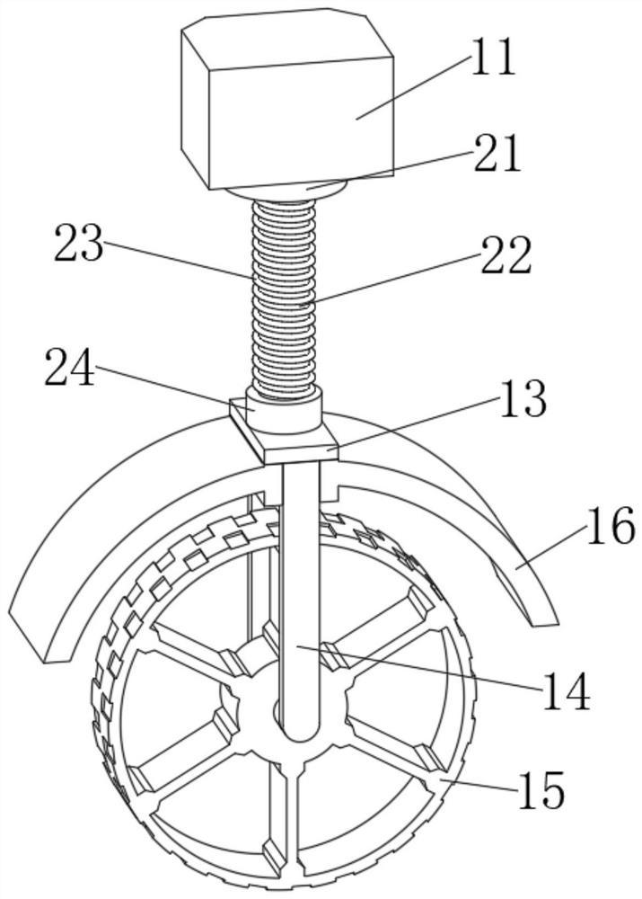
An emergency rescue and firefighting technology, applied in the direction of fire rescue, etc., can solve the problems of no buffer components, large impact force of water flow, affecting the mixing ratio of foam liquid, etc., to avoid jamming and reduce vibration.

Inactive Publication Date: 2021-12-31
秦素红
View PDF0 Cites 0 Cited by
  • Summary
  • Abstract
  • Description
  • Claims
  • Application Information

AI Technical Summary

Problems solved by technology

[0003] The existing forestry fire-fighting emergency foam fire-fighting and rescue devices have the following disadvantages: 1. Most of the existing forestry fire-fighting emergency foam fire-fighting and rescue devices do not have buffer components. The proportional mixer of the proportioner shifts, which affects the mixing ratio of the foam liquid and water, resulting in a decrease in the foam quality; 2. In the existing forestry fire emergency foam fire extinguishing and rescue devices, due to the large impact force of the water flow, most of the spray guns are at a fixed angle, but the fixed angle Angled spray guns cannot meet complex fire-fighting requirements and are impractical; 3. Most of the existing forestry fire-fighting emergency foam fire-fighting and rescue devices directly introduce water into the foam liquid storage tank and mix it with the proportional mixer in the foam liquid storage tank. Foam is generated, but this method cannot control the amount of foam output and the degree of dilution of the foam, which cannot meet the needs of use. Therefore, we propose a fire-fighting emergency rescue device

Method used


Image

  • Fire extinguishing emergency rescue device
  • Fire extinguishing emergency rescue device
  • Fire extinguishing emergency rescue device

Examples


Embodiment Construction

[0026] In order to make the technical means, creative features, goals and effects achieved by the present invention easy to understand, the present invention will be further described below in conjunction with specific embodiments.

[0027] In the description of the present invention, it should be noted that the terms "upper", "lower", "inner", "outer", "front end", "rear end", "both ends", "one end", "another end" The orientation or positional relationship indicated by etc. is based on the orientation or positional relationship shown in the drawings, and is only for the convenience of describing the present invention and simplifying the description, rather than indicating or implying that the referred device or element must have a specific orientation, use a specific Azimuth configuration and operation, therefore, should not be construed as limiting the invention. In addition, the terms "first" and "second" are used for descriptive purposes only, and should not be understood ...


PUM


Abstract

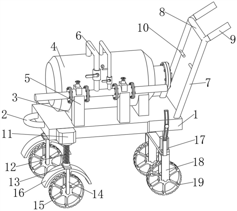
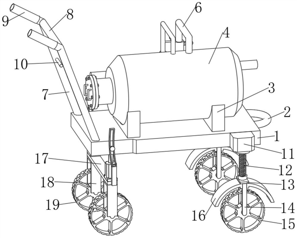
The invention discloses a fire extinguishing emergency rescue device which comprises a mounting plate, a traction ring is fixedly mounted at the left end of the mounting plate, two bilaterally symmetrical first supporting frames are fixedly mounted on the rear portion of the upper end of the mounting plate, a foam liquid storage tank is jointly and fixedly mounted at the upper ends of the two first supporting frames, two bilaterally symmetrical second supporting frames are fixedly mounted on the front portion of the upper end of the mounting plate, a foam production assembly is jointly arranged at the upper ends of the two second supporting frames, the foam production assembly extends into the foam liquid storage tank, two handrails are fixedly mounted on the right portion of the upper end of the mounting plate, the two handrails are symmetrically distributed front and back, and a reinforcing rod is fixedly mounted between the two handrails. According to the fire extinguishing emergency rescue device, the spraying elevation angle of a spraying gun can be adjusted, jolt borne by the foam liquid storage tank during moving can be reduced, the foam output and dilution degree can be adjusted, use is convenient, and the forest land fire extinguishing requirement is met.

Description

technical field [0001] The invention relates to the technical field of fire-fighting equipment, in particular to a fire-fighting emergency rescue device. Background technique [0002] The emergency foam fire extinguishing rescue device is mainly composed of a foam liquid storage tank, a spray gun, a proportional mixer, a hose, and a trolley chassis. It is a new type of environmentally friendly and efficient foam fire extinguishing device. It is easy to operate, flexible and reliable. Strong. In the initial stage of a fire, the device can be driven flexibly to the fire scene for fire extinguishing. The emergency foam fire extinguishing and rescue device can be used independently as a fire protection equipment, and can also be used as an auxiliary rescue function in conjunction with a large fixed foam fire extinguishing system. Emergency foam fire extinguishing and rescue device is an important part of forestry fire fighting equipment. [0003] The existing forestry fire-fi...

Claims


Application Information

Patent Timeline
Patent Type & Authority Applications(China)
IPC IPC(8): A62C5/02A62C31/28
CPCA62C31/28A62C5/02
Inventor 秦素红
Owner 秦素红
Learn More