
Split type auxiliary supporting and discharging device for laser pipe cutting machine

An auxiliary support and pipe cutting machine technology, applied in laser welding equipment, welding equipment, metal processing equipment, etc., can solve the problems of falling danger, high blanking height, impact deformation of pipes, etc., to avoid the danger of falling, support stable, Ensure the effect of the blanking direction

Active Publication Date: 2021-12-31
江苏卡米特激光智能科技有限公司
View PDF11 Cites 1 Cited by
  • Summary
  • Abstract
  • Description
  • Claims
  • Application Information

AI Technical Summary

Problems solved by technology

[0003] The purpose of the present invention is to solve the problem that when the pipe is cut, the height of the pipe is high, and the pipe falls from a high place. The impact of the pipe’s own gravity will cause the pipe to be deformed by impact, affect the product quality, and even cause the danger of falling, causing personnel or accidents. Provide a split type auxiliary support blanking device for laser pipe cutting machine to solve problems such as equipment damage

Method used

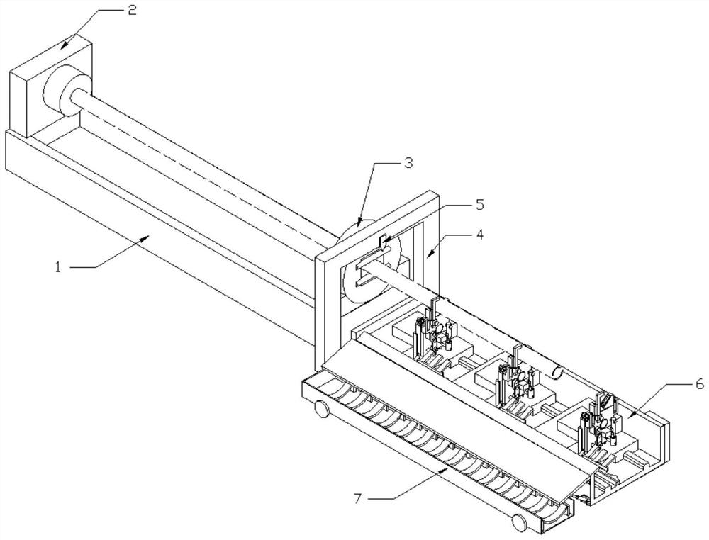

Image

  • Split type auxiliary supporting and discharging device for laser pipe cutting machine
  • Split type auxiliary supporting and discharging device for laser pipe cutting machine
  • Split type auxiliary supporting and discharging device for laser pipe cutting machine

Examples


Embodiment Construction

[0042] The following will clearly and completely describe the technical solutions in the embodiments of the present invention with reference to the accompanying drawings in the embodiments of the present invention. Obviously, the described embodiments are only some, not all, embodiments of the present invention. Based on the embodiments of the present invention, all other embodiments obtained by persons of ordinary skill in the art without making creative efforts belong to the protection scope of the present invention.

[0043] In describing the present invention, it should be understood that the terms "longitudinal", "transverse", "length", "width", "thickness", "upper", "lower", "front", "rear", " The orientation or positional relationship indicated by "left", "right", "vertical", "horizontal", "top", "bottom", "inner", "outer", etc. is based on the orientation or positional relationship shown in the drawings, It is only for the convenience of describing the present invention ...


PUM


Abstract

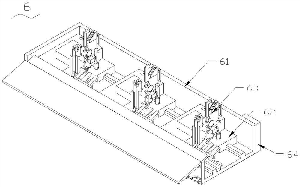
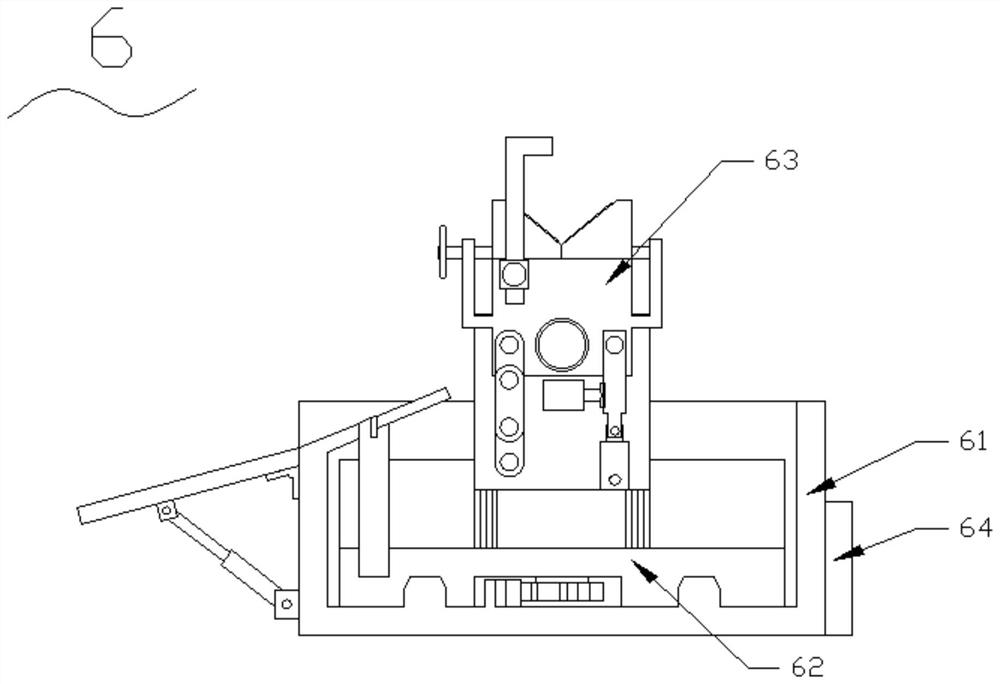
The invention discloses a split type auxiliary supporting and discharging device for a laser pipe cutting machine. The split type auxiliary supporting and discharging device comprises a laser pipe cutting machine base, a movable chuck is arranged at one end of the upper surface of the laser pipe cutting machine base, a fixed chuck is arranged at the other end of the upper surface of the laser pipe cutting machine base, a portal frame is arranged on one side of the fixed chuck, a laser cutting head is arranged on one side face of the portal frame, a supporting and discharging device is arranged at one end of the laser pipe cutting machine base, a material collecting trolley is arranged on one side of the supporting and discharging device, the supporting and discharging device comprises a bottom frame, a plurality of moving devices are arranged inside the bottom frame, supporting and adjusting devices are arranged on the upper surfaces of the moving devices, and a control module is arranged on the outer surface of one side of the bottom frame. According to the split type auxiliary supporting and discharging device, the supporting effect can be achieved when a finished pipe is cut, the situation that a notch is irregular is avoided, the cutting quality is improved, and the situation that the finished pipe is damaged or falls off due to the fact that impact force is too large in the discharging process of the finished pipe can be effectively prevented.

Description

technical field [0001] The invention belongs to the technical field of laser tube cutting machine processing and manufacturing, and in particular relates to a split-type auxiliary support blanking device for a laser tube cutting machine. Background technique [0002] Existing laser pipe cutting machines extend the pipe to be cut to the outside of the pipe cutting machine when cutting, but due to the gravity of the pipe itself, when the pipe is long, it is prone to sag before and after cutting, affecting The shape of the cutting mouth and even the cutting accuracy, the reference document CN201921223073.1 discloses an automatic lifting support blanking device for a laser pipe cutting machine, which mainly reduces the damage to the pipe caused by the waste particles generated during cutting, and also reduces the damage to the pipe itself. The problem of irregular cuts caused by gravity, but in practical applications, when the pipe is blanked, the pipe will fall from a high plac...

Claims


Application Information

Patent Timeline
Patent Type & Authority Applications(China)
IPC IPC(8): B23K26/38B23K26/70
CPCB23K26/702B23K26/38Y02P70/10
Inventor 陈章陈杰井部修
Owner 江苏卡米特激光智能科技有限公司
Learn More