Nonmetal thin material shearing machine

A non-metal, shearing machine technology, used in metal processing and other directions, to achieve smooth loading and unloading, high quality of finished products, and small swing space.

Inactive Publication Date: 2017-04-26
安徽汉邦重工机床制造有限公司
View PDF10 Cites 0 Cited by
  • Summary
  • Abstract
  • Description
  • Claims
  • Application Information

AI Technical Summary

Problems solved by technology

[0006] Aiming at the problem that existing shearing machines are difficult to cut soft and tough non-metallic thin materials such as film, rubber, soft glass, etc., the present invention provides a non-metallic thin material shearing machine, which can complete the above-mentioned non-metallic thin materials. The shearing process of materials is especially suitable for the shearing of rubber. Using this equipment for shearing will not jam the knife, the incision is smooth, and the quality of the finished product is high.

Method used


Image

  • Nonmetal thin material shearing machine
  • Nonmetal thin material shearing machine
  • Nonmetal thin material shearing machine

Examples


Embodiment 1

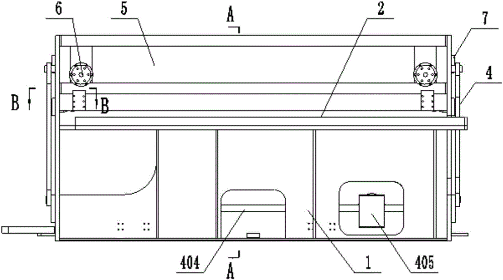
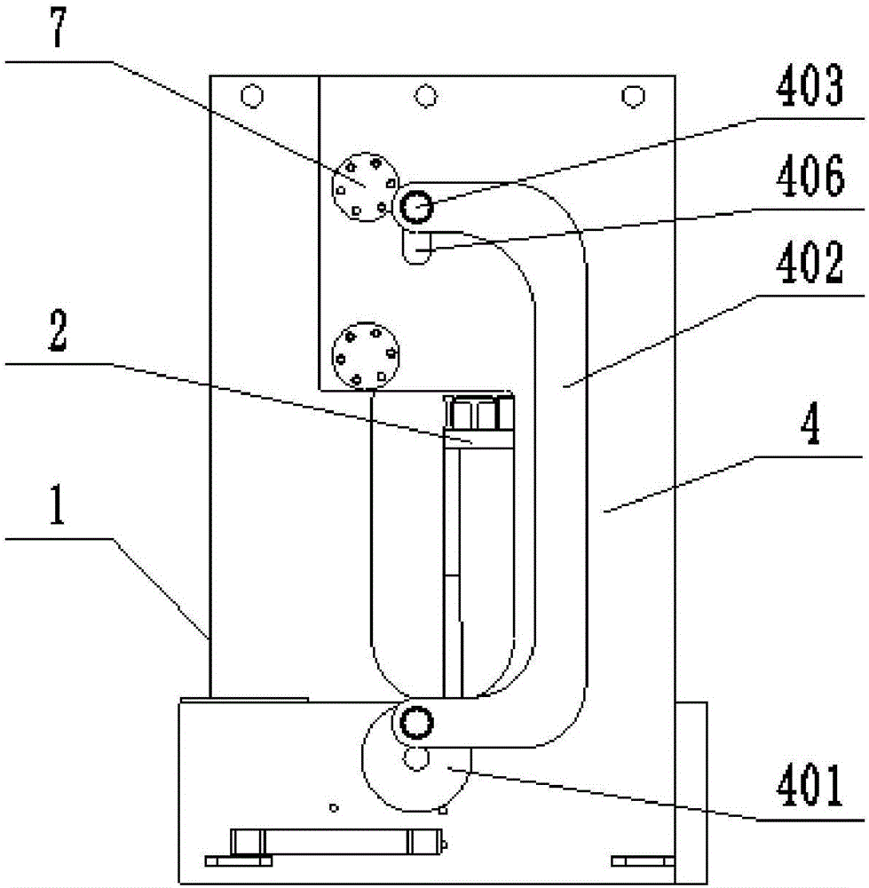
[0046] Such as Figure 1 to Figure 5 As shown, a kind of non-metallic thin material shearing machine of the present embodiment comprises frame 1, workbench 2 and upper knife rest 3, and frame 1 has left and right two wallboards, is respectively left wallboard 101 and right wallboard 101. Wallboard 102, workbench 2 and upper knife rest 3 are located between two wallboards, on workbench 2, lower blade is installed through lower blade seat, and upper blade is installed on the upper knife rest, and the installation structure of blade is prior art The conventional method is the same as that of the common shearing machine, and will not be repeated here.

[0047] In front of the upper knife rest 3, a front panel 5 is installed between the left wallboard 101 and the right wallboard 102, and a front roller assembly 6 is respectively arranged at both ends of the front panel 5, and the front roller assembly 6 is provided with a front roller 640; Both ends of the front surface of the fra...

Embodiment 2

[0052] After long-term practice and summary, when the non-metallic thin material shearing machine in Example 1 is used to shear rubber, the thickness of the sheared rubber is between 0.5 and 2.5 mm, and the gap between the upper and lower blades is between 0.01 and 0.03 mm. During this period, the cutting quality can reach the best. In this example, the rubber of 1mm is taken as an example, the gap between the upper and lower blades is adjusted to 0.02mm, and the equipment in Example 1 is used to cut 1000 times, and no knife jamming occurs. The shearing surface of the sheared rubber is inspected and observed after zooming in. The incision is flat and smooth, without creases, and the shape of the incision is consistent in the length direction, and the overall quality is high.

Embodiment 3

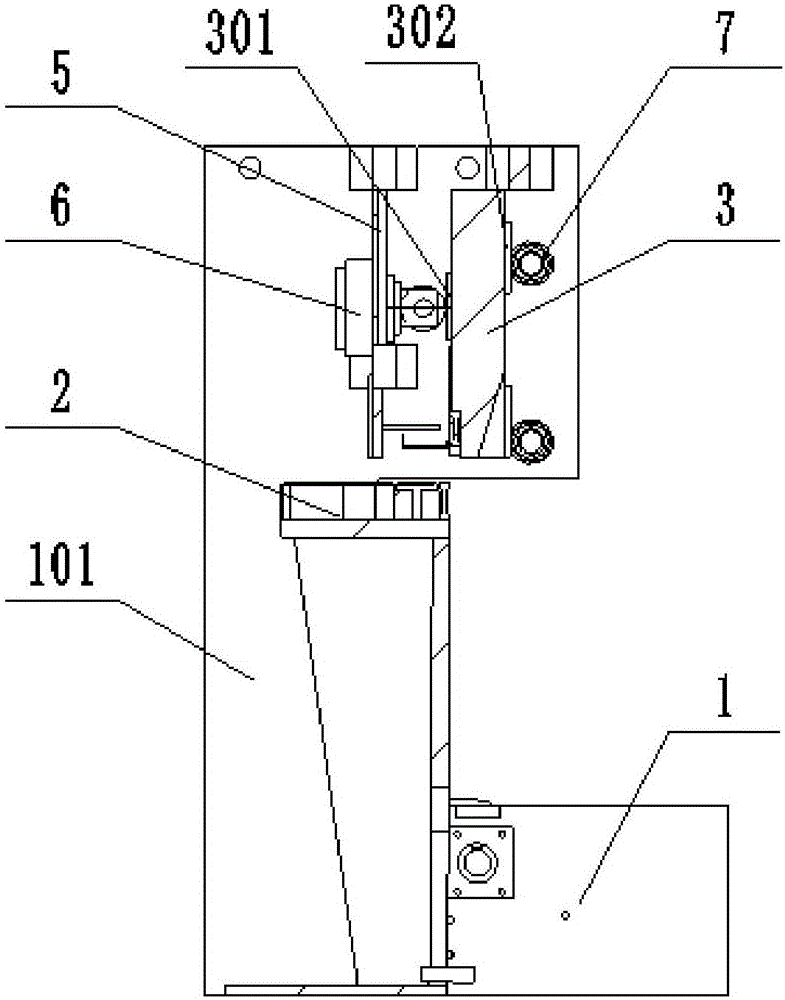
[0054] A kind of non-metal thin material shearing machine of the present embodiment, on the basis of the structure of embodiment 1, the structure of the front roller assembly 6 has been optimized and improved, specifically, as Figure 6 , Figure 7 and Figure 8 As shown, the front roller assembly 6 includes a mounting base 610, a guide rod 620 and a gland 660, wherein the mounting base 610 is installed on the front panel 5, and a through hole is provided in its center, and the rear end of the guide rod 620 is located in the through hole. Among them, the front end of the guide rod 620 is provided with a U-shaped groove, the front roller 640 is located in the U-shaped groove, and is connected to the guide rod 620 through the roller shaft 630, and the roller shaft 630 is fixed by the set screw provided at the front end of the guide rod 620, Thereby avoid roller shaft 630 to drop; Gland 660 is covered on the other end of the through hole of mounting seat 610 by bolt, and spring ...


PUM

PropertyMeasurementUnit
Thicknessaaaaaaaaaa

Abstract

The invention discloses a nonmetal thin material shearing machine, and belongs to the field of soft thin material machining equipment. The nonmetal thin material shearing machine comprises a frame, a worktable provided with a lower blade, an upper cutter frame provided with an upper blade, and cutter frame driving mechanisms; the cutter frame driving mechanisms include driving wheels, connecting rods and motors; one ends of the connecting rods are eccentrically connected with the driving wheels, and the other ends are connected with the upper cutter frame through connecting shafts; the driving wheels are driven through the motors, and drive the connecting rods to drive the upper cutter frame to move up and down, so that the upper blade generates a shearing motion corresponding to the lower blade; two cutter frame driving mechanisms are provided, and are respectively arranged on the outer sides of two wall plates of the frame; two driving wheels are arranged on the wall plates through bearings, and are connected as a whole through driving shafts; and the motors are connected with the driving shafts through gear boxes. The nonmetal thin material shearing machine can finish shearing of such nonmetal thin materials as films, rubber and soft glass, is not easy to clamp cutters, is smooth in incision, high in quality of finished products and adjustable in edge gaps, can adapt to the cutting requirements of materials with different thicknesses, and is high in adaptability.

Description

technical field [0001] The invention belongs to the field of soft thin material processing equipment, and more specifically relates to a non-metal thin material shearing machine. Background technique [0002] A shearing machine is a machine that cuts or cuts materials into required sizes. At present, shearing machines on the market are basically only suitable for cutting various shapes of steel, plates and various metal materials. They are driven by hydraulic pressure and have safety features. The advantages of reliable performance and convenient operation. There are many types of shearing machines. From different perspectives, there are different classification methods. For example, according to the shearing method, it can be divided into transverse shearing and longitudinal shearing; according to the temperature of the sheared steel plate, it can be divided into hot shearing and cold shearing; According to the driving mode of the shearing machine, it is divided into mecha...

Claims


Application Information

Patent Timeline
IPC IPC(8): B26D1/06B26D7/26B26D5/08
CPCB26D1/065B26D5/086B26D7/2628B26D2001/0033
Inventor 张元红
Owner 安徽汉邦重工机床制造有限公司
Why Eureka
Try Eureka