[0028] The present invention will be further explained in conjunction with the accompanying drawings.
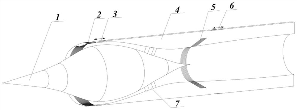
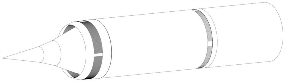
[0029] The present invention is mainly directed to the start and flow matching of the geometric ultrasonic speed shaft symmetrical intake channel, which proposes a MA0-4 supersonic axis symmetric intake and flow regulation method based on a discharge slit controllable switch. .
[0030] A turbine engine flow demand Figure 5 According to the medium dashed line, the lower triangular dashed line is the upper limit of the turbine engine, the upper triangular dashed line is the lower limit of the turbine engine, that is, the traffic demand is a section. The numerical simulation is a geometric (non-discharged sewing) intake trail capture flow is greater than the engine traffic demand, and the minimum starting horse number mA = 3, there is a start and airway / engine flow matching problem. In order to turn the supersonic speed axis symmetrical intake channel work range to 0-4 Mach (only MA> 1, MA = 1-1.5, the intake passage is worked, there is no need to consider the start), that is, the minimum starting horse number reduction Small to MA = 2, and realize the problem of intake / engine flow matching, take the following measures:
[0031] according to Figure 1A and 1b As shown, the MA0-4 supersonic axis symmetric intake passage of the discharged sewing controllable switch of the present invention includes the intake channel center body 1, the intake channel center body 1 is the three-stage cone structure, the intake channel center body 1 The entire flow cover 4 is provided, and there is a passage between the intake center body 1 and the entire flow cover 4, and the airway center body 1 is connected to the entire flow cover 4, and the support 7 is supported by the center symmetry distribution; the entire flow cover 4 is opened There are multi-excreted seams, the seam area of the drain seam is controllable.
[0032] The discharge seam includes the internal pressure segment drain seam 2 and the expanded section drain sewing 5, the inner pressure segment drain sewing 2 is opened at the internal pressure segment of the rectifier cover 4, and the expanded segment drainage seam 5 is opened in the rectifier cover 4. . The internal pressure segments drain 2 and the expanded segment drain seam 5 are all multi-rows.
[0033] A groove is provided at the inner pressure segments in the entire flow cover 4, which is provided in the recess, and the inner pressure segment cylinder 3 can be moved before and after the recess, through the movement The pressure segment cylinder 3 regulates the internal pressure segment drain seam 2 switch state to adjust the seam area; when the internal pressure segment drain sewing 2 is completely opened, the internal pressure segment cylinder 3 is flush and the entire flow cover 4 is flushed, the internal pressure segment The discharge seam 2 is closed, and the front end of the inner pressure section is flush with the entire flow cover 4.
[0034] A groove is provided at the expanded section drain seam 5 on the expanded section drainage 5, which is provided in the recess, and the expanded segment cylinder 6 can move before and after the recess, by moving the expansion segment cylinder. 6 Adjust the expansion section drain seam 5 switch state to adjust the seam area; the expansion section of the cylinder 6 is flat to the entire flow cover when the expanded segment drain seam 5 is completely opened, and the expansion segment drainage 5 is closed when the expansion The front end of the cartridge 6 is flat to the entire flow cover.
[0035] figure 2 In order to discharge the inclination angle θ, the interval D-D, and the discharge joint position and the intake passage are not started, the relative position is shown. The internal pressure segments discharge seam 2 is inclined with respect to the entire flow cover 4, the inner pressure segment discharge seam and the angle θ = 30 ° of the entire flow cover, the width D of the single internal pressure segment drainage seam is 5mm, adjacent internal pressure segments The spacing of the drain is 5 mm. The expanded section drain seam 5 is inclined with respect to the entire flow cover 4, the expanded section drainage sewing and the angle θ = 30 ° of the entire flow cover, the width D of the single expansion segment is 10mm, adjacent expansion segments The interval D is 10 mm.
[0036] image 3 , Figure 4 A cross-sectional view of the axially symmetric intake diameter in the circumference of 0 ° and 45 °. The drain is placed in the circumferential direction of the entire flow cover, the inner ring is 360 ° loop seam, and the outer ring is a central symmetry interval.
[0037]The working principle of the present invention: When the geometric hybrid airway is in the low mach (MA ≤ 2.5), the intake passage does not start, because the sidewall area determined under the design status (mA = 4) is in low mach At the time, the traffic captured by the airway is greater than the flow of the design throat area. Therefore, when the low mach is the number of channels in the inner pressure segment of the intake laret, the airflow plug appears when the low mep is started. The present invention lends the sewing in the internal pressure segment of the plug region, the redundant ultrasonic speed gas stream is introduced into the inside of the whole cube, so that the airway starts; when the airway is working properly, the end of the end is behind the throat. The expansion segment is located in the sub-aerosol flow, mainly on the pressure difference and the seam area discharge, mainly relying on the adjustment of the seam area to change the airway flow.
[0038] Table 1 shows the flow modifier method for the discogenous intake airway based on the discharged seam controllable switch. Specifically:
[0039] When MA <1.5, the discharge is completely closed;
[0040] When MA = 1.5, the internal pressure segment cylinder 3, the internal pressure segment drains sews 14 sewing, regulating flow;
[0041] At mA = 2, the cylinder 3 of the inner pressure segment moves backwards, opens 21 seams, intake starting, and moving the expansion of the cylinder 6 backwards, opens a seam, and adjust the flow rate to match the airway / engine flow.
[0042] When mA = 2.5, the internal pressure segment cylinder 3 moves forward, opens 15 seams, the intake start, maintains the expansion section to open 1 sewing, and adjust the flow to match the airway / engine flow.
[0043] When MA = 3, the internal pressure segment cylinder 3 moves forward, and the internal pressure segments discharge seam is completely closed, and the expansion of the cylinder 6 is moved backwards, and 4 sewers, the adjustment flow is made to match the airway / engine flow.
[0044] When mA = 3.5, the expanded segment cylinder 6 is moved forward, and 2 seams are moved, and the regulatory flow makes the intake passage / engine flow.
[0045] When MA = 4, moving the expansion section of the cylinder 6 forward, close all expansion segments.
[0046] Table 1
[0047]
[0048] Figure 5 Curve of flow coefficient of flow coefficient for different flying mach numbers. The lower triangular dashed line is the upper limit of the turbine engine, the upper triangular dashed line is the turbine engine flow rate, that is, the traffic demand is a section. The circular solid line is the flow coefficient when the geometric intake is started, and the square solid line is the regeneration of the airway flow coefficient (MA = 1.5 external pressure). The shaft symmetrical intake scheme based on the drain sewing controlled switch is designed by the present invention, and the minimum starting horse number of the intake channel is reduced to 2, and the intake channel / engine flow matching target is realized.
[0049] The above is merely the preferred embodiment of the present invention, and it should be noted that several improvements and moisteners can be made without departing from the principles of the invention, these improvements and moisters are also made without departing from the principles of the invention. It should be considered as the scope of the present invention.