Eureka AIR delivers breakthrough ideas for toughest innovation challenges, trusted by R&D personnel around the world.

Pneumatic valve air source redundancy device

A technology of pneumatic valves and redundant devices, applied in the direction of valve devices, valve operation/release devices, valve details, etc., can solve problems such as breaking, affecting production, safety accidents, etc., and achieve the effect of eliminating hidden dangers of accidents

Pending Publication Date: 2021-12-31
石钢京诚装备技术有限公司
View PDF0 Cites 0 Cited by
  • Summary
  • Abstract
  • Description
  • Claims
  • Application Information

AI Technical Summary

Problems solved by technology

In the actual production process, often due to the length of the air source pipe is too long, the air source pipe is prone to aging, fracture, breakage, etc. At this time, the pneumatic valve will have control failure or reset action due to low air source pressure or no air source supply. If it is light, it will affect production, and if it is heavy, it will cause safety accidents

Method used


Image

  • Pneumatic valve air source redundancy device
  • Pneumatic valve air source redundancy device
  • Pneumatic valve air source redundancy device

Examples


Embodiment Construction

[0017] Below in conjunction with accompanying drawing, the present invention will be further described by examples.

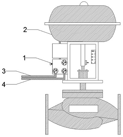
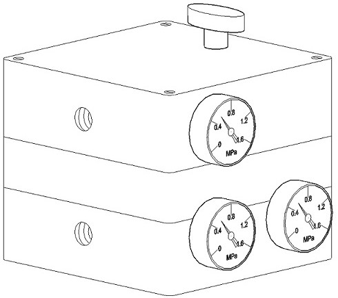
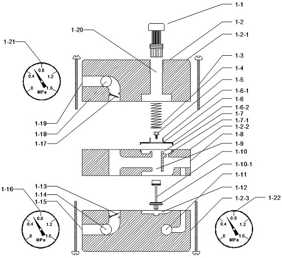
[0018] Refer to attached Figure 1-4 , a pneumatic valve air source redundant device, including pneumatic valve 2, air source A3, air source B4, pressure regulating knob 1-1, housing 1-2, pressure regulating spring 1-4, locking bolt 1-5 , Pressure regulating diaphragm 1-6, Pressure equalizing chamber 1-7, Air outlet chamber 1-8, Pressure regulating column 1-10, Intermediate chamber 1-12, Check valve B1-13, Air inlet chamber B pressure hole 14, Air intake chamber B1-15, check valve A1-17, air intake chamber A pressure hole 1-18, air intake chamber A1-19 and pressure regulating chamber 1-20, the housing 1-2 includes upper, middle, The lower three parts, the upper part of the casing is provided with a pressure regulating chamber 1-20, the pressure equalizing chamber 1-7 is formed between the upper part of the casing and the middle part of the casing, the middle c...


PUM


Abstract

The invention relates to a pneumatic valve air source redundancy device, and belongs to the technical field of pneumatic valves in the metallurgical industry. According to the technical scheme, a pressure regulating cavity (1-20) is formed in the upper portion of a shell, a pressure equalizing cavity (1-7) is formed between the upper portion of the shell and the middle of the shell, a middle cavity (1-12) is formed between the middle of the shell and the lower portion of the shell, an air inlet cavity A (1-19) and an air inlet cavity B (1-15) which are connected with an air source A (3) and an air source B (4) are formed in the left side of the shell, and an air outlet cavity (1-8) connected with a pneumatic valve (2) is formed in the right side of the shell; and the middle cavity (1-12) communicates with the air inlet cavity A (1-19), the air inlet cavity B (1-15) and the air outlet cavity (1-8), and the pressure equalizing cavity (1-7) communicates with the air outlet cavity (1-8). The pneumatic valve air source redundancy device has the advantages that the two paths of air sources can be provided for the pneumatic valve at the same time, and under the condition that one path of air source is not available, the other path of air source can ensure that the pneumatic valve does not have control failure or reset action.

Description

technical field [0001] The invention relates to a pneumatic valve air source redundant device, which belongs to the technical field of pneumatic valves in the metallurgical industry. Background technique [0002] Pneumatic valves are widely used in the industrial field. The principle is to use compressed air as power to drive the piston in the actuator, and rotate or lift the torsion shaft to drive a pneumatic control valve driven by the valve stem. All pneumatic valves are connected to solenoid valves or valve positioners by an air supply pipe, and the valves are driven by actuators. In the actual production process, often due to the length of the air source pipe is too long, the air source pipe is prone to aging, fracture, breakage, etc. At this time, the pneumatic valve will have control failure or reset action due to low air source pressure or no air source supply. If it is light, it will affect production, and if it is heavy, it will cause safety accidents. Contents ...

Claims


Application Information

Patent Timeline
Patent Type & Authority Applications(China)
IPC IPC(8): F16K31/12F17D3/01
CPCF16K31/12F17D3/01
Inventor 牛玉双
Owner 石钢京诚装备技术有限公司
Why Eureka
Eureka Blog
Learn More