
Hydraulic energy equation flow velocity measurement experiment device and method

A technology of flow velocity measurement and energy equation, which is applied in the field of hydraulic energy equation experimental equipment, can solve problems such as difficult to control the regulating valve reasonably, large error in experimental results, unstable readings of piezometric tubes, etc., and achieve simplified experimental steps, Improved accuracy, intuitive and precise effect of flow velocity measurement

Pending Publication Date: 2021-12-31
HOHAI UNIV
View PDF7 Cites 0 Cited by
  • Summary
  • Abstract
  • Description
  • Claims
  • Application Information

AI Technical Summary

Problems solved by technology

[0003] However, the current energy experiment has problems such as time-consuming, cumbersome flow measurement and large error, unstable reading of the piezometric tube, and difficulty in controlling the regulating valve reasonably, all of which will cause errors of varying degrees, resulting in large errors in the final experimental results and failure of the experiment. more likely

Method used


Image

  • Hydraulic energy equation flow velocity measurement experiment device and method
  • Hydraulic energy equation flow velocity measurement experiment device and method
  • Hydraulic energy equation flow velocity measurement experiment device and method

Examples


Embodiment Construction

[0030] The present invention will be further described below in conjunction with the accompanying drawings and specific embodiments. The following examples are only used to illustrate the technical solution of the present invention more clearly, but not to limit the protection scope of the present invention. And the following description is only the preferred implementation mode of the patent of the present invention, it should be pointed out that for those of ordinary skill in the art, without departing from the technical principle of the patent of the present invention, some improvements and deformations can also be made, these Improvements and distortions should also be considered as the protection scope of the patent for the present invention.

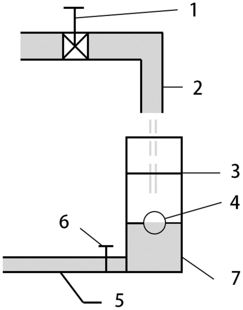
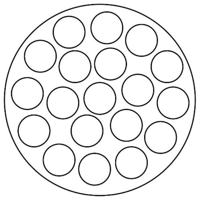
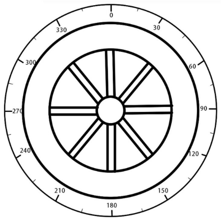
[0031] Such as Figure 1-3 As shown, an experimental device for measuring the flow rate of the hydraulic energy equation, including a flow regulating valve 1, an outlet pipe 2, a porous sieve plate 3, a floating ball 4, a return p...


PUM


Abstract

The invention discloses a hydraulic energy equation flow velocity measurement experiment device and method. The device comprises a flow regulating valve, a water outlet pipe, a porous sieve plate, a floating ball, a water return pipe, a water stop valve and a water storage container, the flow regulating valve is arranged on the water outlet pipe, the water storage container is arranged below the water outlet pipe, and the top of the water storage container is open; water flowing out of the water outlet pipe directly flows into the water storage container, the diameter of the porous sieve plate is slightly smaller than the inner diameter of the water storage container, the porous sieve plate is fixed to the inner wall of the water storage container, and the fixing height is adjustable; the floating ball is arranged in the water storage container and is positioned below the porous sieve plate; the water return pipe is communicated with the water storage container; the water stop valve is arranged on the water return pipe; and the device has the characteristics of simple structure, reusability, low cost and low energy consumption. The flow measurement method converts the water flow velocity into the rising velocity of the floating ball in the water storage device, so that the flow velocity measurement mode is more visual and accurate, the experiment efficiency is improved, the experiment time is saved, and the method is widely applied to various fluid mechanics experiments.

Description

technical field [0001] The invention relates to a hydraulic energy equation experimental device technology, in particular to a hydraulic energy equation flow velocity measurement experimental device and method. Background technique [0002] For the analysis of complex water flow motion, the combination of various angles and methods is required. The energy equation experiment of constant flow is an important part of the current hydraulic experiment. Its items respectively represent three different forms of energy per unit mass of fluid, and its physical meaning is that fluid per unit mass has the characteristic of mechanical energy conservation along the same streamline under the condition of ignoring head loss. [0003] However, the current energy experiments have problems such as time-consuming, cumbersome flow measurement and large errors, unstable readings of the piezometric tubes, and difficulty in controlling the regulating valve reasonably, all of which will cause erro...

Claims


Application Information

Patent Timeline
Patent Type & Authority Applications(China)
IPC IPC(8): G01P5/18G01M10/00G09B23/12
CPCG01P5/18G01M10/00G09B23/12
Inventor 孙洪广范思圆
Owner HOHAI UNIV
Learn More