Zero-carbon-emission fossil fuel power generation method and device system

A technology for fossil fuels and power generation devices, applied in the field of zero-carbon emission fossil fuel power generation methods and device systems, can solve the problems of high cost, zero, slow development, etc., and achieve the effect of omitting transportation costs and omitting transportation links

Pending Publication Date: 2021-12-31
彭斯干
View PDF4 Cites 1 Cited by
  • Summary
  • Abstract
  • Description
  • Claims
  • Application Information

AI Technical Summary

Problems solved by technology

[0003] However, there are currently almost zero commercial-scale CCS projects
It is generally believed that there is not much time left to deal with climate change, and the current CCS technology route is too expensive and the situation of slow development needs to be changed urgently

Method used


Image

  • Zero-carbon-emission fossil fuel power generation method and device system
  • Zero-carbon-emission fossil fuel power generation method and device system
  • Zero-carbon-emission fossil fuel power generation method and device system

Examples


Embodiment 1

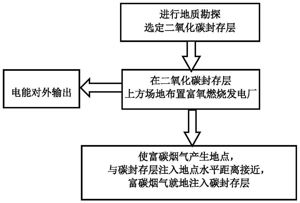
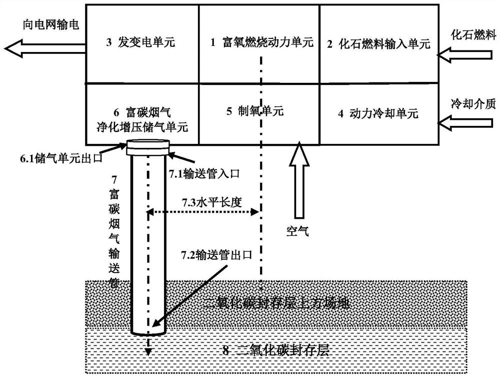
[0036] Embodiment 1: It is the basic embodiment of the zero-carbon emission fossil fuel power generation method of the present invention. as attached figure 1As shown, the steps of the zero-carbon emission fossil fuel power generation method include: conducting geological surveys to select a carbon dioxide storage layer, arranging a fossil fuel power plant on the site above the selected carbon dioxide storage layer, and bubbling the fossil fuel with oxygen in the power plant Oxygen-enriched combustion power generation, generating electric energy and carbon dioxide-rich flue gas, the generated electric energy is transmitted externally, and the generated carbon dioxide-rich flue gas is injected into the carbon dioxide storage layer on the spot; the method of injecting the carbon dioxide storage layer on the spot is to use The place where the carbon dioxide-rich flue gas is generated, the place where the carbon dioxide is injected into the carbon dioxide storage layer, and the h...

Embodiment 2

[0038] Embodiment 2: It is a further embodiment based on Embodiment 1. The carbon dioxide-rich flue gas is injected into the carbon dioxide storage layer on the spot, which is a carbon dioxide-rich gas with a ratio of about 50% of the mass of carbon dioxide to the total mass of the flue gas. The flue gas is injected into the carbon dioxide storage layer on site.

[0039] Another embodiment is that the carbon dioxide-rich flue gas is injected into the carbon dioxide storage layer on-site, that is, the carbon dioxide-rich flue gas whose mass ratio of carbon dioxide to the total mass of the flue gas is about 60% is injected into the carbon dioxide storage layer on-site.

[0040] Another embodiment is that the carbon dioxide-rich flue gas is injected into the carbon dioxide storage layer on-site, that is, the carbon dioxide-rich flue gas whose mass ratio of carbon dioxide to the total mass of the flue gas is about 85% is injected into the carbon dioxide storage layer on-site.

[0...

Embodiment 3

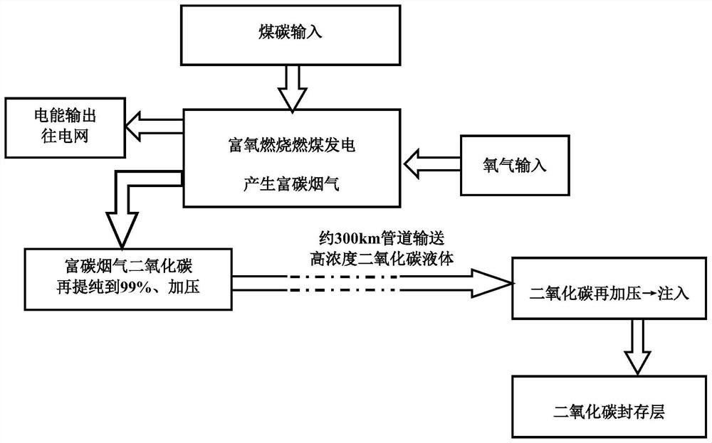
[0042] Embodiment 3: It is another embodiment on the basis of Embodiment 1. The place where the smoke rich in carbon dioxide is produced, and the place where the carbon dioxide is injected into the carbon dioxide sequestration layer, the method for approaching the horizontal distance between the two places is to make A method with a horizontal distance of about 100km between two locations.

[0043] Another embodiment is that the horizontal distance between the place where the carbon dioxide-rich flue gas is generated and the place where the carbon dioxide is injected into the carbon dioxide storage layer is about 50 km.

[0044] Still another embodiment is to make the place where the flue gas rich in carbon dioxide is generated, and the place where the carbon dioxide is injected into the carbon dioxide storage layer, the horizontal distance between the two places is about 20km. Another embodiment is that the horizontal distance between the place where the carbon dioxide-rich f...


PUM

PropertyMeasurementUnit
lengthaaaaaaaaaa

Abstract

The invention discloses a zero-carbon-emission fossil fuel power generation method and device system, and the method comprises the steps: carrying out the geological exploration, selecting a carbon dioxide storage layer, building a fossil fuel power plant at a site above the selected carbon dioxide storage layer, carrying out the oxygen-enriched combustion power generation of oxygen blowing in fossil fuel in the power plant, and transmitting the generated electric energy to the outside. Generated flue gas rich in carbon dioxide is injected into a carbon dioxide storage layer in situ; according to the invention, the horizontal distance between the generation place of the carbon dioxide-rich flue gas and the injection place of the carbon dioxide sequestration layer is close, and the carbon-rich flue gas containing 50%-95% of carbon dioxide is directly injected into the carbon sequestration layer, so that a long-distance transportation link between a carbon capture link and a carbon sequestration link is omitted; and the carbon capture cost and the whole-process CCS cost can be greatly reduced, so that zero-carbon-emission fossil fuel power generation can be economically and feasibly realized.

Description

technical field [0001] The zero-carbon emission fossil fuel power generation method and device system of the present invention belong to the technical field of carbon capture and storage (CCS (Carbon Capture & Storage) to cope with climate change) and the technical field of clean energy. Background technique [0002] To deal with climate change and achieve climate goals, a large number of applications of carbon capture and storage (CCS) are required, especially the realization of a large number of commercial-scale CCS projects in the energy field. There are many existing CCS technology routes, such as image 3 , Figure 4 As shown, it includes three links of carbon capture, transportation and storage; the carbon capture link is to separate the carbon dioxide in the flue gas produced by industrial facilities such as fossil fuel combustion, and requires purification to a general concentration of 99%. For liquid, dense-phase gas or solid carbon dioxide, carbon capture generall...

Claims


Application Information

Patent Timeline
Patent Type & Authority Applications(China)
IPC IPC(8): H01M8/04044H01M8/0668C01B32/50
CPCH01M8/04044H01M8/0668Y02P90/70Y02E60/50
Inventor 彭斯干
Owner 彭斯干
Why Eureka
Try Eureka