Flue gas carbon dioxide trapping system and method based on organic solvent absorption-extraction regeneration cycle

An organic solvent and carbon dioxide technology, applied in chemical instruments and methods, separation methods, gas treatment, etc., can solve the problems of increased absorbent loss cost, damage to system water balance, slow absorption rate, etc., to reduce carbon capture costs, The effect of reducing heat consumption and reducing pollutant emissions

Active Publication Date: 2021-07-13
ZHEJIANG ZHENENG TECHN RES INST
View PDF16 Cites 0 Cited by
  • Summary
  • Abstract
  • Description
  • Claims
  • Application Information

AI Technical Summary

Problems solved by technology

The process system utilizes the aqueous phase CO 2 The advantages of large cycle capacity, thereby reducing regeneration energy consumption, but failed to give full play to the organic phase has a faster CO 2 advantage of the absorption rate, so the absorber's CO 2 slower absorption rate
On the other hand, due to the high volatility of organic solvents, CO 2 In the captur

Method used


Image

  • Flue gas carbon dioxide trapping system and method based on organic solvent absorption-extraction regeneration cycle
  • Flue gas carbon dioxide trapping system and method based on organic solvent absorption-extraction regeneration cycle
  • Flue gas carbon dioxide trapping system and method based on organic solvent absorption-extraction regeneration cycle

Examples


Embodiment 1

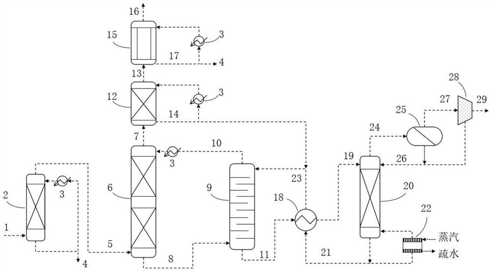
[0035] The flue gas carbon dioxide capture system based on organic solvent absorption-extraction regeneration cycle includes flue gas pretreatment tower 2, absorption tower 6, extraction regeneration tower 9, desorption tower 20, water balance tower 12 and solvent recovery tower 15; The flue gas outlet at the top of the gas pretreatment tower 2 is connected to the flue gas inlet at the bottom of the absorption tower 6; the flue gas outlet at the top of the absorption tower 6 is connected to the flue gas inlet at the bottom of the water balance tower 12; the flue gas outlet at the top of the water balance tower 12 The flue gas inlet that is connected to the bottom of the solvent recovery tower 15 through the flue gas pipeline; the rich liquid outlet of the absorption tower 6 is connected to the rich liquid inlet at the bottom of the extraction regeneration tower 9, and the organic phase outlet at the top of the extraction regeneration tower 9 is connected to the The organic solv...

Embodiment 2

[0044] The working method of the flue gas carbon dioxide capture system based on the organic solvent absorption-extraction regeneration cycle: the lower part of the flue gas pretreatment tower 2 is provided with a flue gas inlet 1, and the flue gas passes through the flue gas pretreatment tower 2, the absorption tower 6, Empty after the water balance tower 12 and the solvent recovery tower 15; the organic solvent absorbs CO in the absorption tower 6 2 , after entering the extraction and regeneration tower 9, it is sent back to the absorption tower 6 for cyclic absorption of CO 2 ; Enriched CO 2 The aqueous solution phase desorbs CO in the desorption tower 20 2 After that, enter the extraction regeneration tower 9, and then send back to the desorption tower 20 to circulate and desorb CO 2 . Specifically include the following steps:

[0045] S1. The flue gas enters from the lower part of the flue gas pretreatment tower 2 and flows from bottom to top, and the aqueous solution...

Embodiment 3

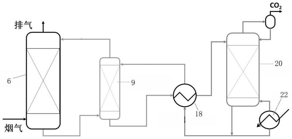
[0055] Such as figure 2 Shown is a three-column CO capture 2 Schematic diagram of the process scheme, using organic solvents to absorb CO in the absorption tower 2, the composition and mass concentration are: 92% DEEA / 2% AEEA / 6% H 2 O. Absorption tower operates at 40°C, after absorbing CO 2 The final organic solvent is sent to the lower part of the extraction regeneration tower, discharged from the top and then returned to the absorption tower to absorb CO 2 .

[0056] CO 2 The aqueous solution phase is used in the desorption tower, and the components and mass concentrations are: 40% AEEA / 40% H2O / 10% DEEA. The desorption tower operates at 120°C to desorb CO 2 The final aqueous solution phase recovers heat through the lean-rich liquid heat exchanger, and sends it to the extraction liquid inlet on the upper part of the extraction regeneration tower. It is discharged from the bottom of the extraction tower from top to bottom, and returns to CO2 through the lean-rich liqui...


PUM


Abstract

The invention relates to a flue gas carbon dioxide trapping system based on organic solvent absorption-extraction regeneration cycle. The flue gas carbon dioxide trapping system comprises a flue gas pretreatment tower, an absorption tower, an extraction regeneration tower, a desorption tower, a water balance tower and a solvent recovery tower; a flue gas outlet in the top of the flue gas pretreatment tower is connected to a flue gas inlet in the lower part of the absorption tower; a flue gas outlet in the top of the absorption tower is connected to a flue gas inlet in the bottom of the water balance tower; a flue gas outlet in the top of the water balance tower is connected to a flue gas inlet in the bottom of the solvent recovery tower through a flue gas pipeline; and a rich liquid outlet of the absorption tower is connected to a rich liquid inlet in the bottom of the extraction regeneration tower; an organic phase outlet in the top of the extraction regeneration tower is connected to an organic solvent inlet in the upper part of the absorption tower. The system disclosed by the invention has the beneficial effects that the advantages that the CO2 absorption rate of an organic solvent in the absorption tower is relatively high and the CO2 circulation capacity of a rich solution in the regeneration tower is large are fully exerted, so that the size of the absorption tower is reduced, the heat consumption of the desorption tower is reduced, and the carbon capture cost is reduced.

Description

technical field [0001] The invention belongs to the technical field of flue gas carbon dioxide capture, and in particular relates to a flue gas carbon dioxide capture system and method based on an organic solvent absorption-extraction regeneration cycle. Background technique [0002] Global warming caused by man-made greenhouse gas emissions is a major challenge facing the world today. As the largest stationary emission source in my country, coal-fired power plants and industrial flue gas CO 2 Capture is an important choice to achieve my country's carbon neutrality goal. Chemical absorption is currently the only method that can capture flue gas CO on a large scale. 2 technical route. [0003] A dilute weak base aqueous solution is most commonly used as flue gas CO 2 Absorbents of chemical absorption technology, such as ethanolamine (MEA) aqueous solution with a mass concentration of 20%-30%, have been applied to million-ton / year coal-fired power plant flue gas CO 2 Capt...

Claims


Application Information

Patent Timeline
IPC IPC(8): B01D53/18
CPCB01D53/18B01D2257/504
Inventor 刘飞祁志福孙士恩申震厉宸希方梦祥
Owner ZHEJIANG ZHENENG TECHN RES INST
Why Eureka
Try Eureka