Unlock instant, AI-driven research and patent intelligence for your innovation.

Bandwidth allocation device and method

A bandwidth allocation and bandwidth technology, which is applied in electrical digital data processing, wireless communication, instruments, etc., can solve problems such as incompatible design of bandwidth utilization, and achieve the effect of low cost and high bandwidth utilization

Pending Publication Date: 2021-12-31
RUIJIE NETWORKS CO LTD
View PDF0 Cites 0 Cited by
  • Summary
  • Abstract
  • Description
  • Claims
  • Application Information

AI Technical Summary

Problems solved by technology

[0005] The present invention provides a bandwidth allocation device and method to solve the problem in the prior art that when a port is compatible with two bandwidth outputs of 200G and 400G, it cannot achieve a compatible design with high bandwidth utilization under low cost conditions

Method used


Image

  • Bandwidth allocation device and method
  • Bandwidth allocation device and method
  • Bandwidth allocation device and method

Examples


Embodiment 1

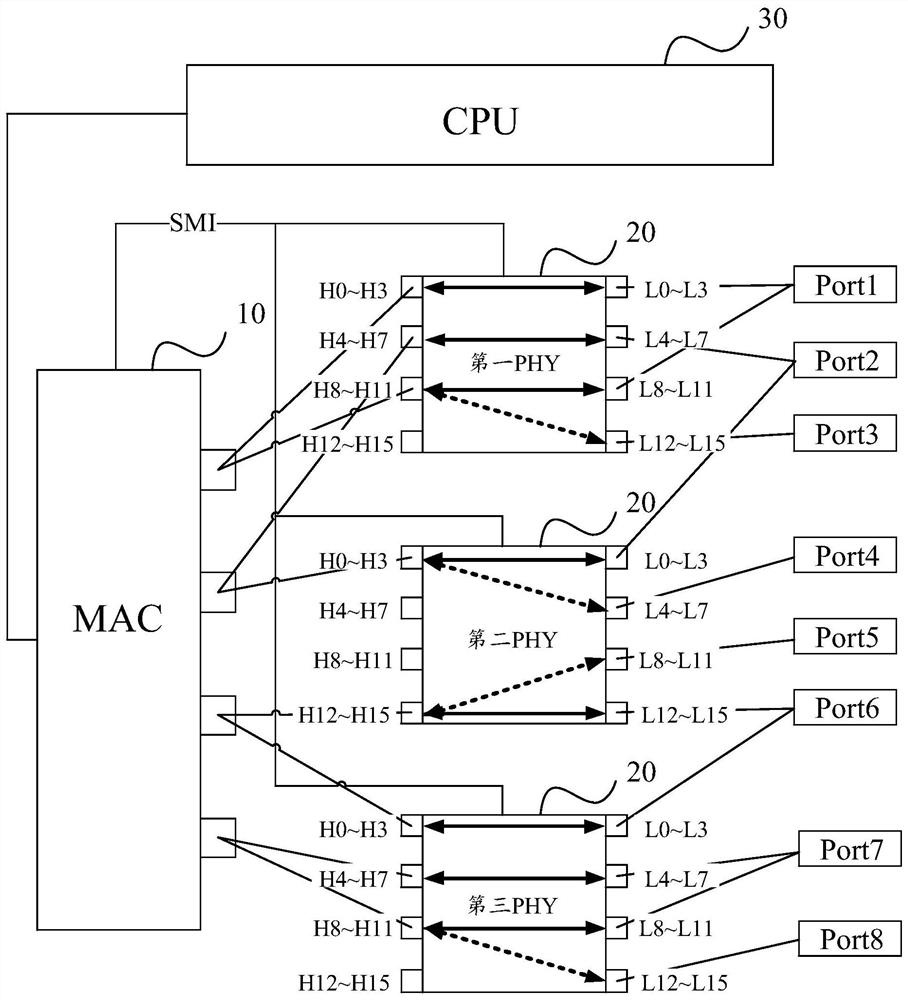
[0071] Embodiment 1: Configure 8 ports with a bandwidth of 200G.

[0072] When configuring 8 ports with a bandwidth of 200G, that is figure 2 The output bandwidth to be allocated for each output port of the MAC 10 is 400G, and the output bandwidth of ports Port1-Port8 is 200G. Combine below figure 2 and Table 1 illustrate this embodiment.

[0073] figure 2 A schematic diagram of a working mode of a bandwidth allocation device is provided for the present invention. Table 1 is a table of a working mode of the PHY. from figure 2 As can be seen from Table 1, the first output port of the MAC 10 outputs 200G bandwidth to be allocated to the host-side serial bus channels H0-H3 of the first PHY and the host-side serial bus channels H8-H11 of the first PHY respectively; The second output port of MAC 10 outputs 200G bandwidth to be allocated to the host-side serial bus channels H4-H7 of the first PHY and the host-side serial bus channels H0-H3 of the second PHY2 respectively; ...

Embodiment 2

[0078] Embodiment 2: Configure four ports with a bandwidth of 400G.

[0079] When configuring 4 ports with a bandwidth of 400G, that is image 3 The to-be-allocated bandwidth output by each output port of the MAC 10 is 400G, and the output bandwidth of ports Port1, Port2, Port6, and Port7 is 400G. Combine below image 3 and Table 2 illustrate this embodiment.

[0080] image 3 A schematic diagram of another working mode of the bandwidth allocation device is provided for the present invention. Table 2 is a table of another working mode of the PHY. The working process of the MAC 10 is the same as that of Embodiment 1 above, and will not be repeated here.

[0081] from image 3 It can be seen from Table 2 that the CPU 30 respectively controls the path conduction between the host-side serial bus channels H0-H3 of the first PHY and the line-side serial bus channels L0-L3, and the host-side serial bus channels of the first PHY The path between the row bus channels H4-H7 and t...

Embodiment 3

[0085] Embodiment 3: Configure two ports with a bandwidth of 400G and four ports with a bandwidth of 200G.

[0086] When configuring two ports with a bandwidth of 400G and four ports with a bandwidth of 200G, that is Figure 4 The output bandwidth to be allocated for each output port of the MAC 10 is 400G, the output bandwidth of ports Port1 and Port2 is 400G, and the output bandwidth of Port5, Port6, Port7, and Port7 is 200G. Combine below Figure 4 and Table 3 illustrate this embodiment.

[0087] Figure 4 A schematic diagram of another working mode of the bandwidth allocation device is provided for the present invention. Table 3 is a table of another working mode of the PHY. The working process of the MAC 10 is the same as that of Embodiment 1 above, and will not be repeated here.

[0088] The CPU 30 respectively controls the conduction of the paths between the host-side serial bus channels H0-H3 of the first PHY 20 and the line-side serial bus channels L0-L3, and the ...


PUM


Abstract

The invention provides a bandwidth allocation device and a method. Each output port of an MAC (Media Access Control) outputs a to-be-allocated bandwidth, a CPU (Central Processing Unit) controls a path between a host-end serial bus channel and a line-end serial bus channel of a PHY (Physical Layer) to be switched on or switched off according to a configuration requirement, and the PHY allocates and outputs the to-be-allocated bandwidth. A group of line end serial bus channels of the PHY and a group of serial bus channels in at least two groups of line end serial bus channels share a group of host end serial bus channels, and a second port packaged by the line end serial bus channels of the PHY is compatible with a first type of optical module and a second type of optical module. Therefore, the path between the host end serial bus channel and the line end serial bus channel is controlled to be switched on or switched off through the CPU, and the high bandwidth utilization rate under the condition of low cost can be achieved.

Description

technical field [0001] The present invention relates to the technical field of wireless communication, in particular to a bandwidth allocation device and method. Background technique [0002] With the commercialization of 5G, coupled with the rapid development of cloud computing, big data, Internet of Things, artificial intelligence and other information technologies and the digital transformation of traditional industries, as well as the rapid construction of data centers, the number of optical modules interconnected within and between data centers and bandwidth requirements are growing explosively. Ports on access switches and aggregation switches have transitioned from 40G to 100G or higher bandwidth port interconnection; interconnection ports on data center switches have gradually transitioned from 100G to 200G and 400G. Since 2019, both 200G and 400G are growing at a rate exceeding 100G, especially the demand for 400G. [0003] Based on the current market demand, the ...

Claims


Application Information

Patent Timeline
IPC IPC(8): H04W72/04G06F13/42
CPCH04W72/0453G06F13/4282
Inventor 林干李明纬
Owner RUIJIE NETWORKS CO LTD