Novel electronic engineering control cabinet convenient to maintain

A technology of electronic engineering and control cabinets, applied in the direction of electrical equipment casings/cabinets/drawers, electrical components, casings/cabinets/drawer components, etc., can solve problems such as inconvenient maintenance and narrow operable space, and achieve Easy to maintain and ensure stable operation

Inactive Publication Date: 2021-12-31
费燕
View PDF1 Cites 0 Cited by
  • Summary
  • Abstract
  • Description
  • Claims
  • Application Information

AI Technical Summary

Problems solved by technology

[0004] However, in actual application technology, most of the existing engineering rollers are equipped with brake devices, which can realize that the control cabinet body can be fixed and move freely; method, due to the narrow operating space, there is also the problem of inconvenient maintenance

Method used


Image

  • Novel electronic engineering control cabinet convenient to maintain
  • Novel electronic engineering control cabinet convenient to maintain
  • Novel electronic engineering control cabinet convenient to maintain

Examples


Embodiment 1

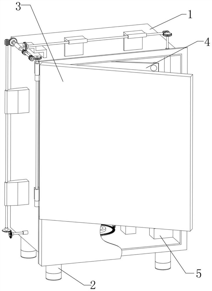
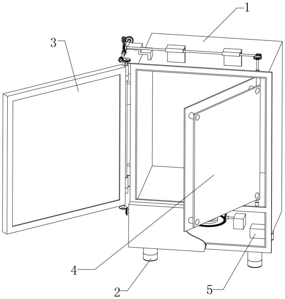
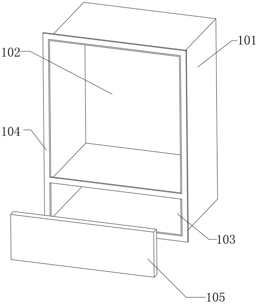
[0042] The present invention realizes the maintenance of engineering control cabinet components and parts such as figure 1 , figure 2 , image 3 , Figure 5 , Figure 8 , Figure 9 and Figure 10 As shown, the array of anchor bases 201 in the multi-purpose anchor assembly 2 is uniformly fixed on the bottom of the main cabinet 101 in the cabinet assembly 1, the central shaft seat 208 is located at the middle position of the bottom of the main cabinet body 101, and the central shaft seat 208 The middle rotation is connected with a central shaft 202, the central bevel gear 203 is plugged and fixed at the lower end of the central shaft 202, the central connection bevel gear 209 is plugged and fixed at the upper end of the central shaft 202, and one side of the central connection bevel gear 209 is meshed with a driving bevel gear 210, the driving bevel gear 210 is axially connected to the driving motor 211, and the driving motor 211 is fixed on the bottom surface of the inner...

Embodiment 2

[0049] The present invention realizes the free movement of engineering control cabinet main body movement example as figure 1 , figure 2 , image 3 , Figure 4 , Figure 5 , Figure 6 and Figure 7 As shown, each group of anchor bases 201 in the multi-purpose anchor assembly 2 is slidably installed with a lifting column 213, and one side of the lifting column 213 is provided with a top socket 214, and the side wall of the anchor base 201 corresponds to the top socket 214. Adjusting bolts 207 are threaded on the position, and the rear ends of each group of adjusting bolts 207 are plugged and fixed with linkage shafts 205, and the arrays of linkage bevel gears 204 are respectively inserted and fixed at the other end of the corresponding linkage shafts 205, and the central bevel gear 203 and Groups of interlocking bevel gears 204 mesh, and the lower ends of each group of lifting columns 213 are rollingly connected with balls 215;

[0050] When the door leaf 302 is opened b...


PUM


Abstract

The invention provides a novel electronic engineering control cabinet convenient to maintain, and belongs to the technical field of engineering control cabinets. The control cabinet comprises a cabinet body assembly, multipurpose foot assemblies, a door leaf assembly, an electronic panel assembly and a wireless communication module which are integrally arranged in the cabinet body assembly. A plurality of groups of multipurpose foot assemblies are arranged on the bottom surface of the main cabinet body, lifting columns are arranged in foot bases, and the lower ends of the lifting columns are in rolling connection with balls; a door leaf in the door leaf assembly can be synchronously driven to be opened by starting a driving motor; when the door leaf is opened, a fixed panel in the electronic panel assembly can be screwed out of an electric appliance cavity by taking a panel rotating shaft as a center, so that an engineer can conveniently maintain an electric appliance; and when the fixed panel is rotated to the outside of the electric appliance cavity, a central bevel gear synchronously drives a linkage bevel gear to rotate, so that the lifting columns are downwards ejected through screw-thread fit of adjusting bolts and adjusting bolt positions, the ball is ejected out of the outer bottom surface of a bottom cover, and the movement of the engineering control cabinet in the maintenance process is facilitated.

Description

technical field [0001] The invention relates to the technical field of engineering control cabinets, in particular to a novel electronic engineering control cabinet that is easy to maintain. Background technique [0002] The electronic engineering control cabinet is an indispensable part of industrial production equipment. Most of the components are installed in a fixed position inside the control cabinet. In daily maintenance and regular inspection, the space in the control cabinet, the installation position of components and other factors When installing and replacing faulty components, short circuits in the control cabinet are prone to occur, and there is a risk of accidental electric shock, which will not only damage components, but also may cause injury to operators. [0003] As the prior art (CN 112533415 A) discloses a new type of electronic engineering control cabinet, comprising a control cabinet body, one side of the control cabinet body is hinged with a cabinet do...

Claims


Application Information

Patent Timeline
IPC IPC(8): H05K5/02
CPCH05K5/0234H05K5/0217H05K5/0204H05K5/0247
Inventor 费燕杨璐
Owner 费燕
Why Eureka
Try Eureka