
Persistent guide wire identification

A technology for image recognition and medical equipment, applied in the field of navigation systems, which can solve the problems of not easily conforming to clinical workflow, time-consuming, troublesome, etc.

Pending Publication Date: 2021-12-31
KONINKLJIJKE PHILIPS NV
View PDF1 Cites 0 Cited by
  • Summary
  • Abstract
  • Description
  • Claims
  • Application Information

AI Technical Summary

Problems solved by technology

But handcrafting features in this way can be cumbersome and time-consuming, and may not easily fit into clinical workflows

Method used


Image

  • Persistent guide wire identification
  • Persistent guide wire identification
  • Persistent guide wire identification

Examples


Embodiment Construction

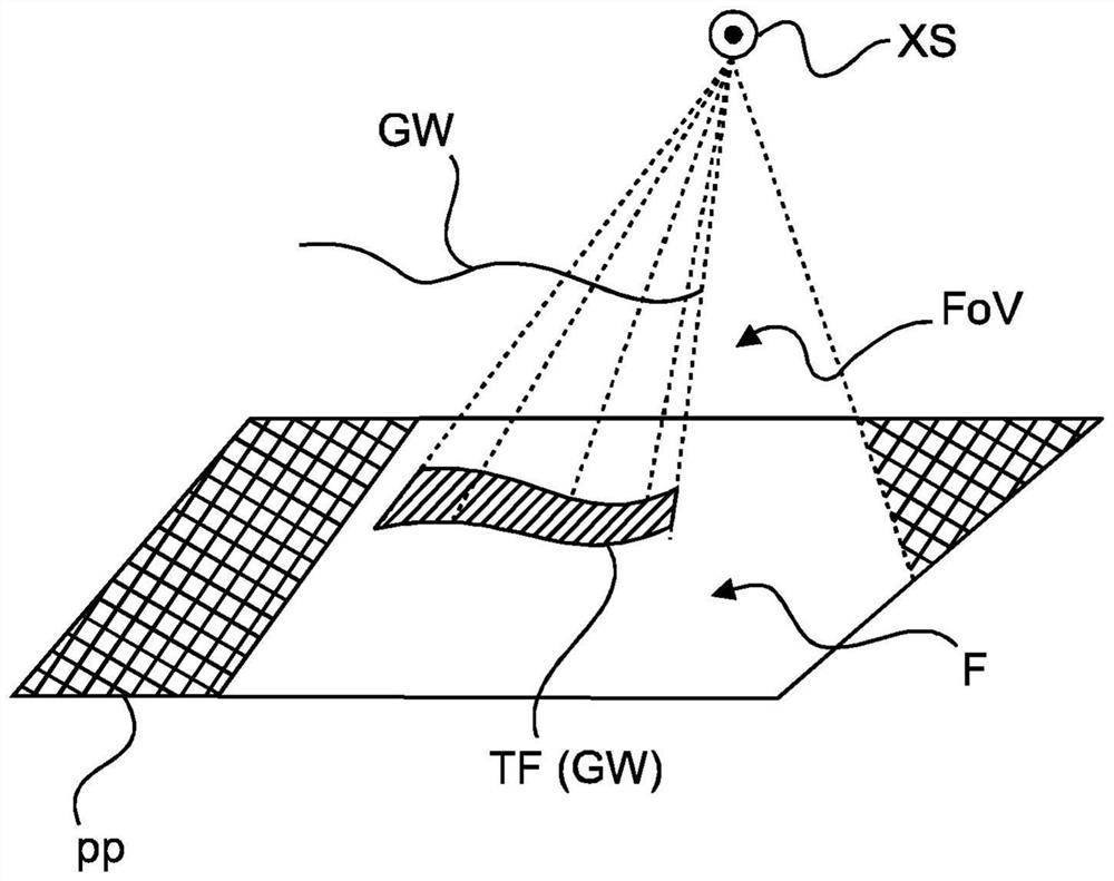
[0054] refer to figure 1 , shows a schematic diagram of an arrangement AR for image-based navigation support, which is preferably used in the context of medical interventions.

[0055] The arrangement AR comprises an imaging device IA, in particular an X-ray imaging device, operable by a user for obtaining an X-ray image F of the patient's internal structure at a region of interest ROI i . A region of interest ROI may be a human heart, lung or another organ or group of organs.

[0056] Image F i (also sometimes referred to herein as a sequence of frames) may be displayed to the user in real time on the display device DD as a moving picture or video feed.

[0057] The imaging arrangement AR also includes an image processing system IPS for processing images. Broadly, an image processing system IPS is a computerized system that processes a received image to include in the image one or more visual indicators or labels representing a corresponding or multiple medical devices. ...


PUM


Abstract

A system (IPS) for supporting image-based navigation, comprising: an input interface (IN) for receiving one or more input images acquired by an X-ray imager (IA) whilst two or more medical devices (GW1, GW2) are present in a field of view (FoV) of the X-ray imaging apparatus; an image identifier (ID) that identifies the two or more medical devices based on image information in the one or more images; a tagger (TGG) that associates a respective, unique, tag with each of at least two of the two or more medical devices (GW1, GW2) so identified; and a graphics display generator (GDG) that effects displaying on a display device (DD) the one or more input images in a video feed, with the tags included.

Description

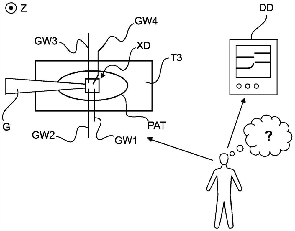
technical field [0001] The invention relates to a system for supporting image-based navigation, a method for supporting image-based navigation, a computer program element and a computer-readable medium. Background technique [0002] In certain medical interventions, such as percutaneous coronary intervention (PCI), clinicians sometimes need to introduce several (eg, three or more) medical devices or tools (eg, guidewires) into a patient. For example, a clinician may start to treat a stenosis in one branch of a coronary artery and then switch to another branch where two guidewires must be used to treat the bifurcation before switching back to the previous branch. In other use cases, clinicians can use both antegrade and retrograde guidewires to manage chronic total occlusions (CTO). These and similar interventions sometimes require the presence of multiple devices at the lesion. [0003] During these difficult and demanding interventions, the clinician needs to switch from ...

Claims


Application Information

Patent Timeline
Patent Type & Authority Applications(China)
IPC IPC(8): A61B5/00A61B90/90G16H30/40G06T7/246G16H40/63
CPCG16H40/63G16H30/40A61B2090/376A61B90/37A61B90/92A61B90/94A61B6/485A61B6/484A61B6/4435A61B6/032A61B34/20A61B2034/2051A61B6/12A61B6/463
Inventor V·M·A·奥夫雷R·弗洛朗
Owner KONINKLJIJKE PHILIPS NV
Learn More