Hydraulic box girder inner mold disassembling and assembling trolley

A technology of hydraulic box and inner mold, applied in bridges, bridge construction, bridge parts, etc., can solve the problems of inconvenient, fast and efficient disassembly, inability to disassemble bolts or steel bars quickly, and single function, and achieve the effect of easy disassembly.

Active Publication Date: 2022-01-04
江苏月生达机械制造有限公司
View PDF6 Cites 0 Cited by
  • Summary
  • Abstract
  • Description
  • Claims
  • Application Information

AI Technical Summary

Problems solved by technology

[0007] Aiming at the deficiencies in the prior art, the present invention provides a trolley for removing and assembling the inner mold of the hydraulic box girder, which solves the problem that: the existing box girder needs to be disassembled and assembled during use, and the traditional dismantling trolley cannot be used in the case of the box girder. The quick disassembly of anchor rods or steel bars, the functionality is relatively simple, and it is not convenient for quick and efficient disassembly

Method used


Image

  • Hydraulic box girder inner mold disassembling and assembling trolley
  • Hydraulic box girder inner mold disassembling and assembling trolley
  • Hydraulic box girder inner mold disassembling and assembling trolley

Examples


Embodiment 1

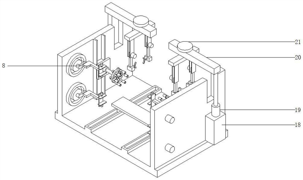
[0032] Embodiment 1, an electromagnetic guide rail 12 is vertically arranged in the middle of the column plate 2, and a movable block is embedded inside the electromagnetic guide rail 12, and a square plate 13 is vertically connected to the outside of the movable block, and a hydraulic cylinder is arranged at the outer middle of the square plate 13 Two 14, the output end of the hydraulic cylinder two 14 is connected with the ring disc 15, and several upright rods are equidistantly arranged on the ring disc 15, and the outer end of the upright rod is connected with the post tube 16, and the inside of the post tube 16 is hollow, through Electromagnetic guide rail 12 is used to drive square plate 13 and hydraulic cylinder 2 14 to move up and down, and anchor rods and steel bars can be dismantled into column pipe 16 for easy disassembly.

[0033] The inboard that is positioned at ring disk 15 is also provided with motor two 17, and the output end of motor two 17 is connected with v...

Embodiment 2

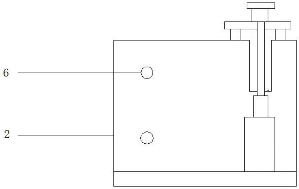
[0035] In the second embodiment, the fastening structure includes a strip plate 22, and a stand frame 23 is arranged symmetrically on both sides of the strip plate 22. The inside of the stand frame 23 is hollow and a motor 24 is arranged outside the bottom end. The output end of four 24 is connected with connecting rod 25, and the outer end of connecting rod 25 is also connected with hydraulic cylinder four 26, and the output end of hydraulic cylinder four 26 is connected with buckle plate 27, through this design, motor four 24 can be used to adjust the connecting rod 25 angle, use hydraulic cylinder 4 26 to adjust the clamping strength of pinch plate 27.

[0036] The pinch plate 27 is one of arc shape or strip shape, which is convenient for clamping and fixing the steel bar or the anchor rod.

Embodiment 3

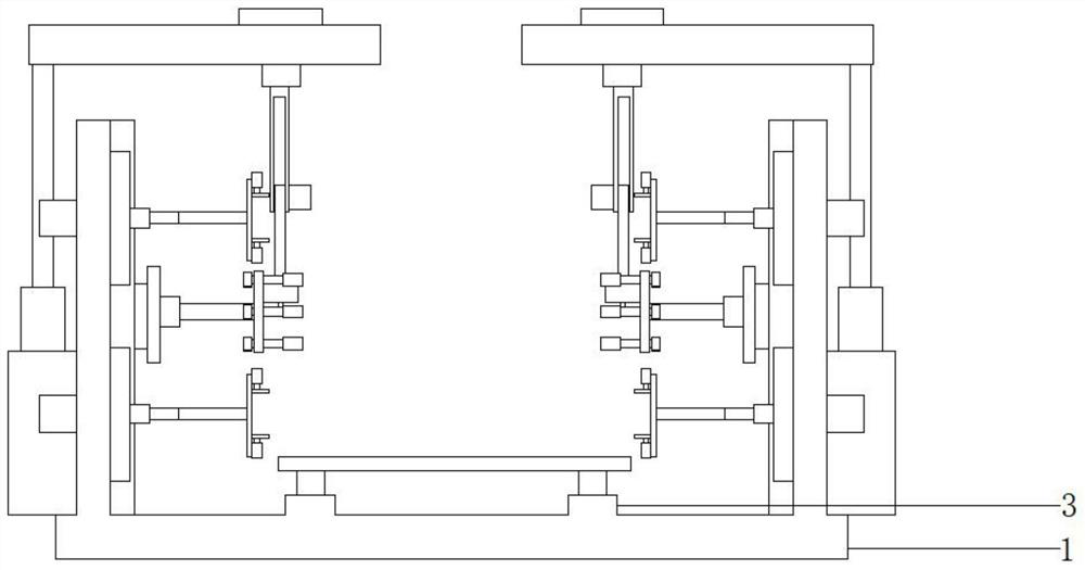
[0037] Embodiment 3, the load-bearing assembly includes a top pressure plate 28 and a bottom pressure plate 29, and the bottom of the bottom pressure plate 29 is provided with two insertion rods 30, and the two insertion rods 30 are inserted into the corresponding guide rail frame 3, and the top pressure plate 28 and the bottom pressure plate 29 There are also several buffer structures arranged between them, which can play the role of support and load bearing.


PUM


Abstract

The invention discloses a hydraulic box girder inner mold disassembling and assembling trolley which comprises a supporting seat plate, stand column plates are symmetrically arranged on the two sides of the top of the supporting seat plate, two guide rail frames are symmetrically arranged on the top of the supporting seat plate, bearing assemblies arranged on the tops of the guide rail frames, two clamping structures are arranged on the inner walls of the stand column plates, each clamping structure comprises a column disc, the column disc is in a cylinder shape, an annular groove is formed in the column disc, an ingot is further arranged in the middle of the column disc, a first motor is further arranged at the outer end of the ingot, a linkage plate is connected with the output end of the first motor, a guide block is arranged on the inner side of the linkage plate, the guide block is embedded into the annular groove, the outer side of the guide block is further connected with a guide column, the outer end of the guide column is connected with a base plate, and the base plate is in a cuboid shape and is symmetrically provided with first hydraulic cylinders. The steel bar and the anchor rod of the box girder can be conveniently and rapidly detached, and the practicability is high.

Description

technical field [0001] The invention relates to the technical field of bridge processing equipment, in particular to a trolley for disassembling and assembling hydraulic box girder inner molds. Background technique [0002] A kind of beam in bridge engineering, the interior is hollow, with flanges on both sides of the upper part, similar to a box, hence the name. Single box, multi-box, etc. [0003] The box girder of reinforced concrete structure is divided into prefabricated box girder and cast-in-place box girder. The prefabricated box girder combined with the bridge erecting machine can be erected after the completion of the substructure, which can speed up the progress of the project and save the construction period; the cast-in-place box girder is mostly used for large continuous bridges. Commonly divided by materials, there are two main types, one is prestressed reinforced concrete box girder, and the other is steel box girder. Among them, the prestressed reinforced...

Claims


Application Information

Patent Timeline
Patent Type & Authority Applications(China)
IPC IPC(8): E01D21/00E01D19/00E01D2/04
CPCE01D21/00E01D19/00E01D2/04
Inventor 丁威力
Owner 江苏月生达机械制造有限公司
Why Eureka
Try Eureka