Pole pit tamping device for electric power engineering

A compaction device and a technology for electric power engineering, applied in the field of electric power engineering, can solve the problems of poor compaction effect, influence, trouble, etc., and achieve the effects of simple and reliable structure, long service life, and easy market promotion.

Active Publication Date: 2022-01-04
STATE GRID HEBEI ELECTRIC POWER CO LTD +2
View PDF3 Cites 2 Cited by
  • Summary
  • Abstract
  • Description
  • Claims
  • Application Information

AI Technical Summary

Problems solved by technology

[0005] The object of the present invention is to provide a rod pit compacting device for electric power engineering, to solve the problem that the existing rod pit compacting device for electric power engineering usually adopts various equipments alone. It is troublesome to tamp the bottom of the pole pit, the surface of the pole pit and the periphery of the pole pit, and it is a technical problem that tamping each place separately will affect each other, making the overall tamping effect not good

Method used


Image

  • Pole pit tamping device for electric power engineering
  • Pole pit tamping device for electric power engineering
  • Pole pit tamping device for electric power engineering

Examples


Embodiment 1

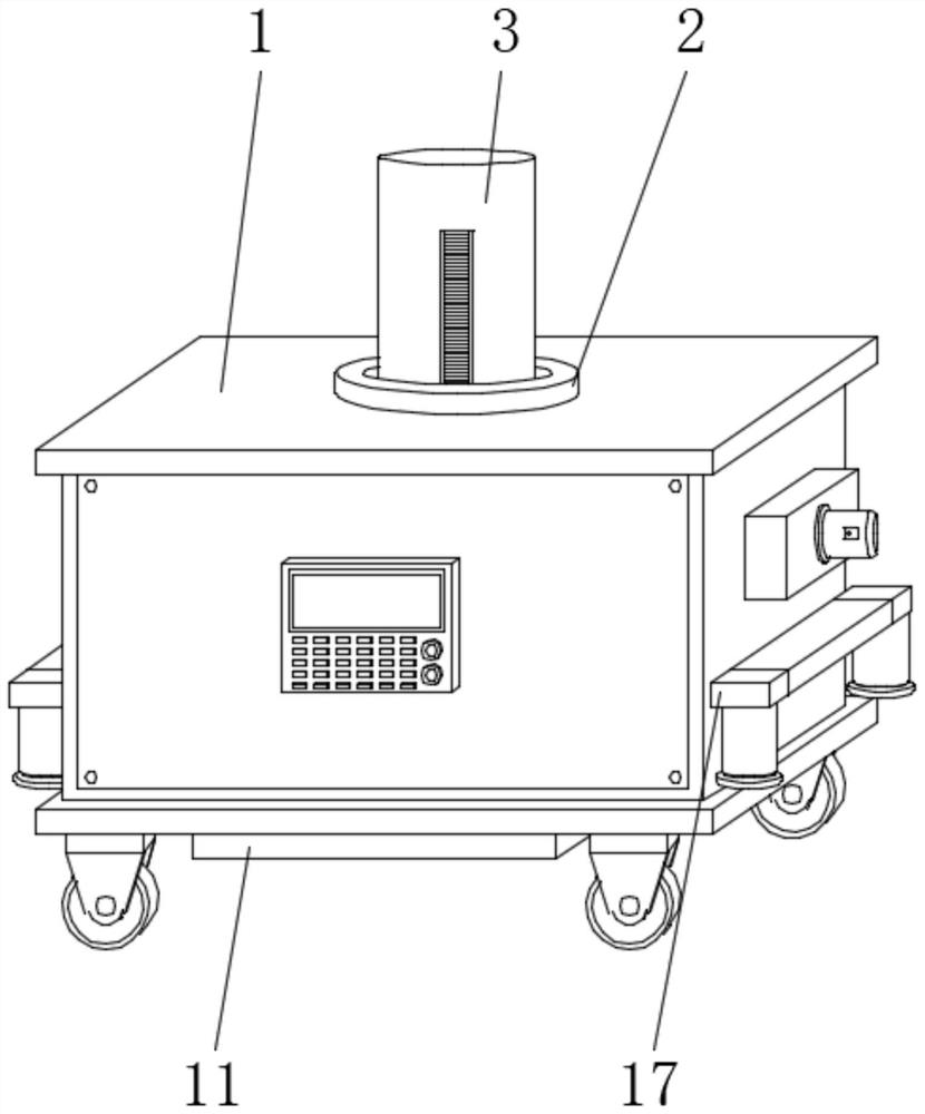
[0041] A pole hole compaction device for electric power engineering, such as Figure 1-3 shown, including:

[0042] Conveyance car body 1, the interior of the transport car body 1 is provided with a guide sleeve 2, the interior of the guide sleeve 2 is provided with a lifting assembly, and the lower end surface of the transport car body 1 is provided with a ground compacting device; and

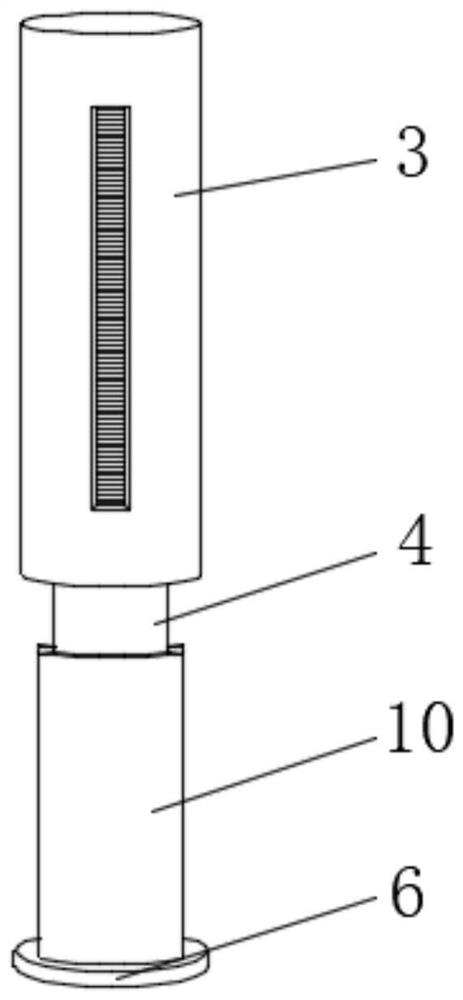
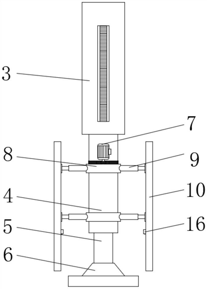
[0043]The tamping column 3 is movably installed in the guide sleeve 2, the tamping column 3 is connected with the lifting assembly, the lower end surface of the tamping column 3 is provided with an installation sleeve 4, and the outer surface of the installation sleeve 4 is provided with an adjustment assembly, adjusting A rod pit inner wall tamping assembly is installed on the assembly, and the inside of the installation sleeve 4 is provided with a lifting column 5, and the bottom end of the lifting column 5 is provided with a pressure plate 6 for compacting the bottom plate of the rod pit; ...

Embodiment 2

[0047] A rod pit compaction device for electric power engineering, such as Figure 1-3 As shown, compared with Embodiment 1, Embodiment 2 also has the following structure:

[0048] The rotating assembly includes a servo motor 7 and two sets of rotating disks 8. The two sets of rotating disks 8 are movably mounted on the outer surface of the installation sleeve 4 through bearings. The servo motor 7 is fixedly installed on the outer surface of the installation sleeve 4. The assembly is connected to one set of rotating discs 8 .

[0049] The servo motor 7 drives the rotating disc 8 to rotate, thereby driving the rotating disc 8 to rotate around the installation sleeve 4, thereby changing the angle of the lateral adjustment assembly, thereby changing the position of the arc-shaped plate 10, so that the arc-shaped plate 10 is completely in line with the rod The inner surface of the rod pit is contacted, and the inner surface of the rod pit is compacted.

[0050] The transmission ...

Embodiment 3

[0058] A rod pit compaction device for electric power engineering, such as Figure 1-7 As shown, compared with the second embodiment, the third embodiment also has the following structure:

[0059] The ground compacting device comprises a lifting frame and a compacting plate 11. The upper end of the compacting plate 11 is fixedly connected with the inner bottom surface of the transport vehicle body 1 through the lifting frame. Through the opening, the lower end of the tamping column 3 passes through the opening.

[0060] The lifting frame can also be replaced by an existing lifting structure, such as a hydraulic lifting column.

[0061] The lifting assembly includes two groups of lifting parts, and the two groups of lifting parts are installed inside the guide sleeve 2. The front end of the outer surface of the tamping column 3 and the rear end of the outer surface thereof are provided with guide grooves, and the lifting parts are located in the inside of the guide groove.

...


PUM


Abstract

The invention discloses a pole pit tamping device for electric power engineering, and belongs to the field of electric power engineering. The pole pit tamping device comprises a conveying vehicle body and a tamping column, a guide sleeve is arranged in the conveying vehicle body, a lifting assembly is arranged in the guide sleeve, and a ground tamping device is arranged on the lower end face of the conveying vehicle body; and the tamping column is movably installed in the guide sleeve, the tamping column is connected with the lifting assembly, an installation sleeve is arranged on the lower end face of the tamping column, and an adjusting assembly is arranged on the outer surface of the installation sleeve. According to the pole pit tamping device for the electric power engineering, pit tamping can be carried out on the surface of a pole pit, the bottom surface of the pole pit and the ground around the pole pit at a time, multiple times of pit tamping is not needed, the pole pit tamping speed is high, the pole pit tamping efficiency is relatively high, the pole pit tamping device can tamp pole pits of different sizes, the applicability is high, the use effect is good, people can conveniently calibrate the position of the pole pit tamping device for the electric power engineering, and a better use prospect is brought.

Description

technical field [0001] The invention relates to the field of electric power engineering, in particular to a rod pit tamping device for electric power engineering. Background technique [0002] Electric power engineering refers to projects related to the production, transmission and distribution of electric energy. The links of power generation, power transmission, power transformation, power distribution, and power consumption are integrated into an organic whole. An extremely complex physical engineering system with hierarchical division of labor; [0003] Power engineering will build a distribution network during power distribution and transmission. When building a distribution network, it is necessary to erect poles. During the erection of poles, the pole pits need to be compacted. In order to facilitate people to tamp the pole pits, people invented poles for power engineering. pit compaction device; [0004] Existing rod pit tamping devices for power engineering have c...

Claims


Application Information

Patent Timeline
Patent Type & Authority Applications(China)
IPC IPC(8): E02D3/046
CPCE02D3/046
Inventor 张维徐彦杰陈朝辉郭世龙李梦杰
Owner STATE GRID HEBEI ELECTRIC POWER CO LTD
Why Eureka
Try Eureka