Supercharge Your Innovation With Domain-Expert AI Agents!

Lock mechanism with state indication function

A technology of state indication and lock mechanism, which is applied in the field of lock mechanism that can display the state of the lock, and can solve problems such as complex manufacturing process assembly, limited rotation angle of the lock, and poor structural stability of the indicator.

Pending Publication Date: 2022-01-04
WENZHOU YEEKA LOCK TECH CO LTD
View PDF1 Cites 0 Cited by
  • Summary
  • Abstract
  • Description
  • Claims
  • Application Information

AI Technical Summary

Problems solved by technology

For example, the "Latch Mechanism with Status Indicator" disclosed in the patent document CN 201780000951.0 filed by Southco Corporation has a cover that can be installed to surround the latch between the latch position and the unlocked position. The central axis is rotated on the shell, and the indicator is inserted between the cover and the shell. For ease of use, there are usually two symmetrically designed indicators in practical applications. The indicator and the cover are in a covering relationship, and the indicator is Installed on the cover to rotate with the cover, a guide structure (groove 46 in the document) is provided on the housing, so that as the cover is rotated, the indicator is guided by the guide structure and deployed to the covering position at least partially protruding from the cover and It is folded to the state of being covered by the cover, so as to achieve the status indication function; in this solution, in order to ensure the stable operation of the indicator, the manufacturing process of the accessories driven by the groove guide structure under the design of the groove guide structure and the corresponding assembly are relatively complicated
In the literature, in the specific embodiment 2, the installation structure that the indicator is pivotally mounted on the housing and does not rotate with the cover is also disclosed, but there are defects that the rotation angle of the lock is limited or / and the structural stability of the indicator is poor

Method used


Image

  • Lock mechanism with state indication function
  • Lock mechanism with state indication function
  • Lock mechanism with state indication function

Examples


Embodiment Construction

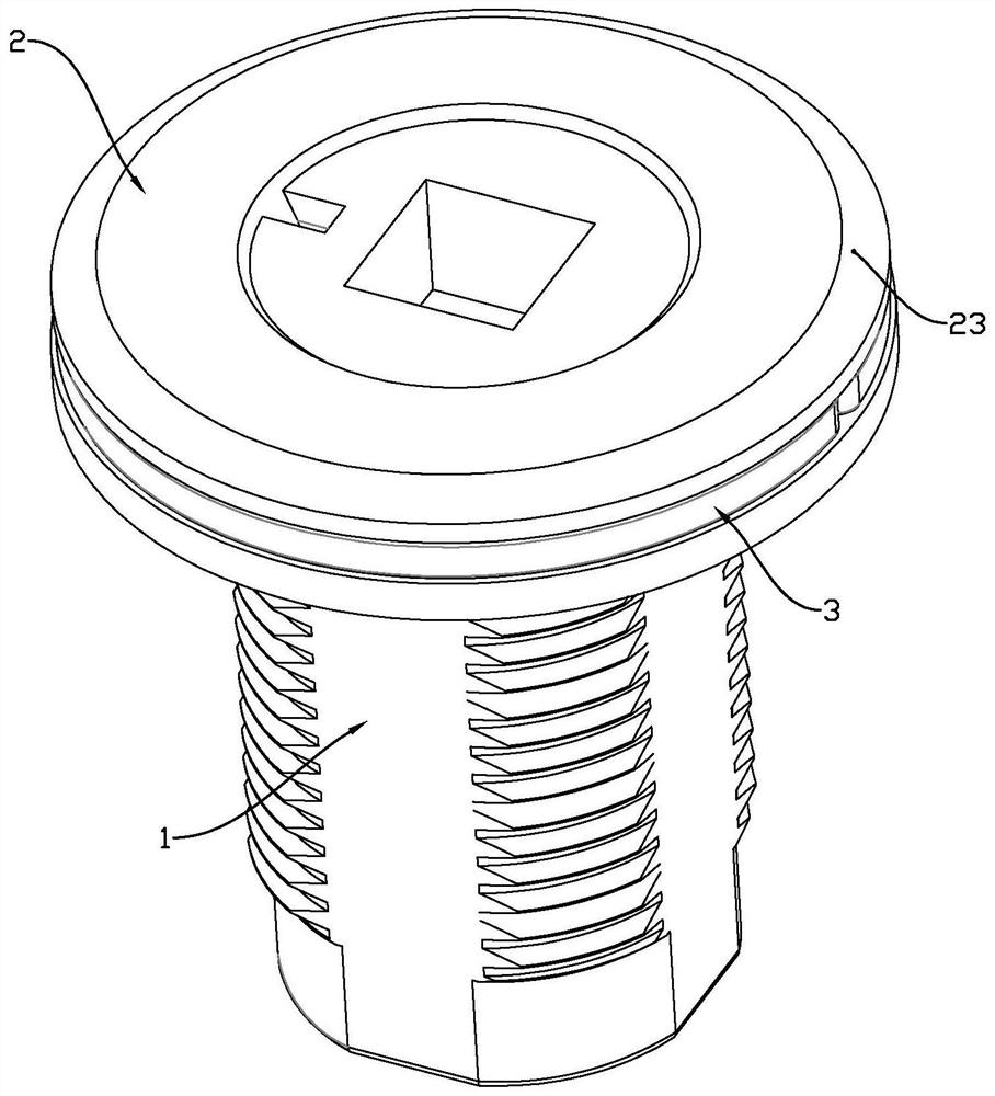
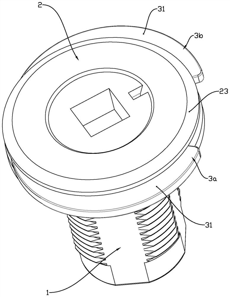
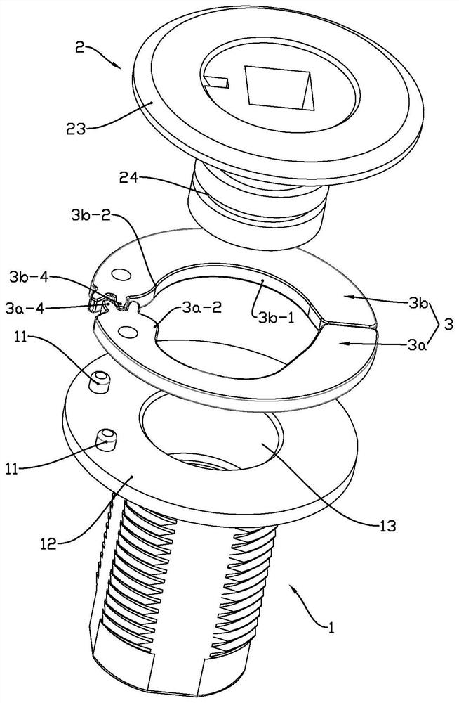
[0021] See attached Figure 1~8 , a lock mechanism with a state indication function disclosed in the present invention, comprising a housing 1, a cover 2 and an indicator 3, the cover 2 has a central axis 21, and is installed to surround the The central axis moves relative to the housing 1. The indicator 3 is inserted between the cover 1 and the housing 2. The indicator 3 has an indicating portion 31 in a covering relationship with the cover 1. The indicator 3 is Pivotably mounted on the housing 1 around a protrusion 11 , the indicator 3 moves from the central axis 21 relative to the cover 2 when the cover 2 is rotated from the latched position to the unlocked position. Move radially outward, so that the indicating portion 31 of the indicator 3 is no longer in a covering relationship with the cover; the cover corresponds to the unlocking and latching action of the locking mechanism, and the cover 2 rotates from the latched position to the unlocked position At this time, the i...


PUM


Abstract

The invention relates to a lock mechanism with a state indication function. The lock mechanism comprises a shell, a cover and an indicator, and the indicator comprises an active indicator and a passive indicator which are circumferentially arranged along a central axis. The driving indicator is provided with a cam matching surface extending in the circumferential direction of the central axis and a stopping end located at the end, corresponding to a pivoting center of the driving indicator, of the cam matching surface, and a radial side protruding part slides along the cam matching surface so that the driving indicator can pivot around a protrusion to leave the central axis of the cover. A radial side convex part pushes and presses the stopping end of the active indicator and promotes the active indicator to pivot around the protrusion to a recovery position where an indicating part is covered by the cover, and the passive indicator is in linkage connection with the active indicator through a tooth transmission device, so that the passive indicator is synchronously unfolded and folded along with the active indicator. The lock mechanism has the advantages of simple structure, convenience in assembly and stable structure.

Description

technical field [0001] The invention relates to a lock mechanism, in particular to a lock mechanism capable of displaying the status of the lock. Background technique [0002] In some applications it is desirable to know whether the mechanism is latched or unlocked. For example, the locks of doors used to secure compartments of coaches or trains may be checked before commencing a journey. If the lock is not locked properly, luggage belonging to passengers may be accidentally lost if the door is opened during transport, or stolen during the journey if the storage compartment is not properly secured and left unattended. [0003] In order to solve the above problems, a lock with a state display function is designed and applied. For example, the "Latch Mechanism with Status Indicator" disclosed in the patent document CN 201780000951.0 filed by Southco Corporation has a cover that can be installed to surround the latch between the latch position and the unlocked position. The ...

Claims


Application Information

Patent Timeline
IPC IPC(8): E05B41/00E05B83/16
CPCE05B41/00E05B83/16E05B83/22E05C3/042E05B35/008
Inventor 项文广李乾兴周燕义卫斯凡邵建局
Owner WENZHOU YEEKA LOCK TECH CO LTD
Features
  • R&D
  • Intellectual Property
  • Life Sciences
  • Materials
  • Tech Scout
  • Unparalleled Data Quality
  • Higher Quality Content
  • 60% Fewer Hallucinations
Learn More