Atmospheric pollution gas detection system
A gas detection system and gas technology, applied in the field of air pollution gas detection systems, can solve the problems of inconvenient particle and dust handling, low accuracy, and small sampling volume, so as to achieve easy detection and cleaning, accurate detection results, and increased The effect of capacity
- Summary
- Abstract
- Description
- Claims
- Application Information
AI Technical Summary
Problems solved by technology
Method used
Image

Examples
Embodiment 1
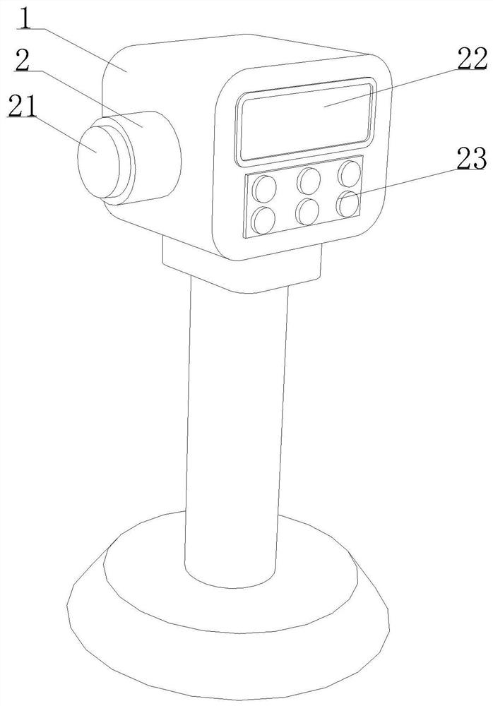
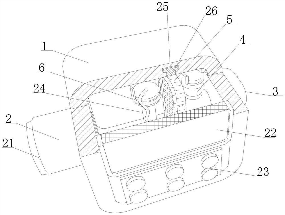
[0032] like Figure 1-6 As shown, the present invention provides an air pollution gas detection system, including a gas collection shell 1, the left and right sides of the gas collection shell 1 are embedded with an intake pipe 2 and an exhaust pipe 3, and the right end of the intake pipe 2 is detachably connected There is a sealing cover 21, the exhaust pipe 3 extends in the inner cavity of the gas collection shell 1, and the left end of the exhaust pipe 3 is provided with a negative pressure pump 4, and the center of the inner cavity of the gas collection shell 1 is provided with a constant potential electrolytic sensor 6, And the inner cavity of the gas collection shell 1 is provided with a guide frame 5 on the right side. When the air pollution gas detection system is in operation, the sealing cover 21 connected to the right end of the intake pipe 2 is disassembled, and the left end of the control exhaust pipe 3 is provided with a The negative pressure pump 4 works so that...
Embodiment 2
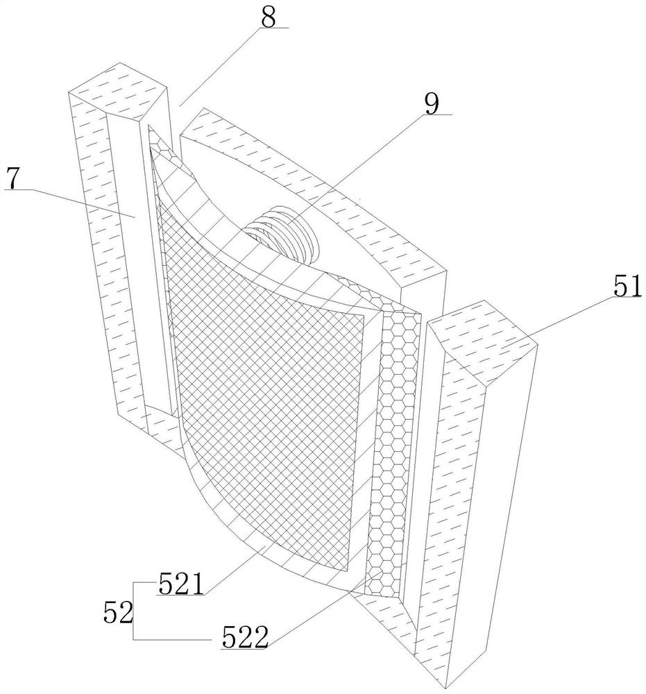
[0035] like Figure 1-6As shown, on the basis of Embodiment 1, the present invention provides a technical solution: preferably, the left and right ends of the arc-shaped fixing frame 51 are horizontally provided with a circulation groove-8, and the circulation groove-8 is connected with the arc-shaped groove 7 Interconnected, the side of the connecting frame body 521 close to the constant potential electrolytic sensor 6 is provided with a flow tank 2 10, the center of the inner wall of the flow tank 10 is provided with a filter 11, and the right side of the inner wall of the flow tank 10 is provided with a sponge Adsorption cushion layer 12, in the process of gas discharge, the gas needs to pass through the particle collection frame 52 in the shape of an arc, and the filter screen 11 and the sponge adsorption cushion layer 12 arranged in the circulation groove 2 10 provided on the surface of the particle collection frame 52 respectively The particles and dust mixed in the gas ...
Embodiment 3
[0038] like Figure 1-6 As shown, on the basis of Embodiment 1, the present invention provides a technical solution: preferably, the left and right sides of the inner wall of the limiting groove 15 are all embedded with a magnetic block 17, and the left and right sides of the outer surface of the collection box 16 are both Embedded with two magnetic blocks 18, the magnetic poles of the first magnetic block 17 and the second magnetic block 18 are opposite to each other, and the tops on the left and right sides of the inner wall of the limit groove 15 are movably connected with a single guide vane 20 by setting a limit rotating shaft 19. When the filter screen 11 drives and connects the sponge adsorption pad 12 to bounce, the particles and dust adhering to the surface vibrate and enter the collection box 16 installed inside the limiting groove 15, and the filter screen 11 and the sponge adsorption pad The layer 12 has a cleaning effect, and the magnetic force connection between ...
PUM
 Abstract
Description
Claims
Application Information
 - Generate Ideas
- Intellectual Property
- Life Sciences
- Materials
- Tech Scout
- Unparalleled Data Quality
- Higher Quality Content
- 60% Fewer Hallucinations
Browse by: Latest US Patents, China's latest patents, Technical Efficacy Thesaurus, Application Domain, Technology Topic, Popular Technical Reports.
© 2025 PatSnap. All rights reserved.Legal|Privacy policy|Modern Slavery Act Transparency Statement|Sitemap|About US| Contact US: help@patsnap.com