
Adjustable power divider

A technology of power divider and No. 1, applied in the field of adjustable power divider, can solve the problems of not taking into account the important cooling of the interface part, the inconvenience of users of heat dissipation fins, and the damage.

Active Publication Date: 2022-01-04
NANJING HUAMAI TECH +1
View PDF7 Cites 0 Cited by
  • Summary
  • Abstract
  • Description
  • Claims
  • Application Information

AI Technical Summary

Problems solved by technology

[0005] In order to make up for the deficiencies of the existing technology, when the existing adjustable power divider is working, the heat dissipation fins on the power divider are likely to cause inconvenience to the user and even cause injury; in addition, no consideration is given to cooling the interface part ; The present invention proposes an adjustable power divider

Method used


Image

  • Adjustable power divider
  • Adjustable power divider
  • Adjustable power divider

Examples


Embodiment approach

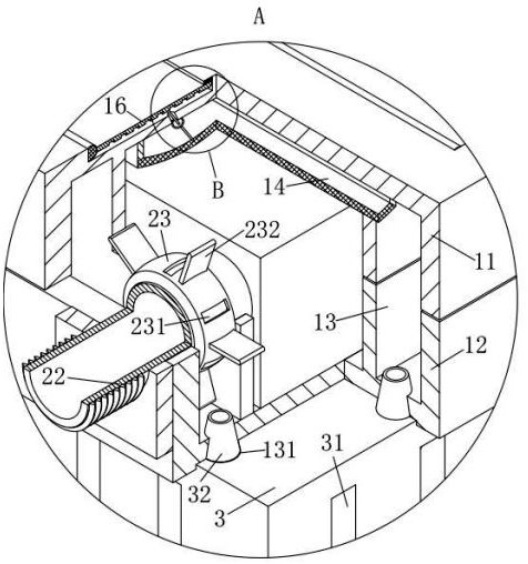
[0033]As a specific embodiment of the present invention, the outer surface of the cooling jacket 23 is uniformly provided with a group of driving plates 232, the No. 1 groove 231 is located in the gap between the driving plates 232, and the number of driving plates 232 is an odd number .

[0034] When working, when the flowing air flow hits the driving plate 232, the driving plate 232 is impacted and drives the cooling jacket 23 to rotate; A pair of symmetrical driving plates 232 makes the impact force received by the cooling jacket 23 in a direction symmetrical to the central axis uneven, ensuring that the cooling jacket 23 can continue to rotate under the impact of the air flow; the rotating cooling jacket 23 The air in the gap between the cooling jacket 23 and the interface 2 is accelerated to rotate, so that the heat on the interface 2 is fully transferred to the air; , the cooling air flow fully flows into the cooling jacket 23 under the guidance of the driving plate 232...


PUM


Abstract

The invention belongs to the technical field of power dividers, and relates to an adjustable power divider. The adjustable power divider comprises a shell, interfaces and a radiator; the shell is formed by splicing an upper shell and a lower shell, and a working circuit is arranged in the shell; the interfaces comprise an input interface and output interfaces, the input interface is installed on one side of the shell, and the number of the input interface is one; and the other side of the shell is uniformly provided with a group of output interfaces. The radiator, an air inlet groove, a first cavity, a first pipe and an air outlet groove are arranged, a fan in the radiator is started, so that external air flows into the radiator through the air inlet groove under the action of the fan and flows into the first cavity through the first pipe, and flowing-in cooling airflow impacts cooling fins and then flows into the outside; and in the process, the cooling airflow brings heat to the outside while flowing out of the air outlet groove, so that the temperature in the shell is effectively controlled.

Description

technical field [0001] The invention belongs to the technical field of power dividers, in particular to an adjustable power divider. Background technique [0002] A power divider is a device that divides the energy of one input signal into two or multiple outputs with equal or unequal energy, and can also conversely combine the energy of multiple signals into one output, which can also be called a combiner at this time. A certain degree of isolation should be guaranteed between the output ports of a power divider. Power divider is also called overcurrent divider. It is divided into two types: active and passive. It can evenly distribute one signal to several outputs. Generally, each channel has a few dB attenuation. The signal frequency is different, and the attenuation of the divider is different. Different, in order to compensate for the attenuation, a passive power divider is made after adding an amplifier. The internal circuit components of the power divider will gener...

Claims


Application Information

Patent Timeline
Patent Type & Authority Applications(China)
IPC IPC(8): H01P5/04H01P1/30
CPCH01P5/04H01P1/30
Inventor 杨勇林洁顾晓峻张家军
Owner NANJING HUAMAI TECH
Features
  • Generate Ideas
  • Intellectual Property
  • Life Sciences
  • Materials
  • Tech Scout
  • Unparalleled Data Quality
  • Higher Quality Content
  • 60% Fewer Hallucinations
Learn More