Magnetic steel array of permanent magnet dual-rotor motor

A dual-rotor motor, magnetic steel array technology, applied in the field of magnetic steel array, can solve the problems of output torque decrease, torque density increase, increase manufacturing difficulty, etc., to reduce torque pulsation, reduce cogging torque, The effect of high torque density

Pending Publication Date: 2022-01-04
雷厉
View PDF0 Cites 0 Cited by
  • Summary
  • Abstract
  • Description
  • Claims
  • Application Information

AI Technical Summary

Problems solved by technology

[0004] Although the existing dual-rotor motor can reduce the cogging torque and torque ripple to a certain extent by cutting permanent magnets, oblique poles, optimizing tooth shape or using complex driving algorithms, it will inevitably lead to a loss of output torque. Decrease and increase manufacturing difficulty, therefore, the existing dual-rotor motor has the problem of inconsistency between torque density improvement and torque ripple suppression

Method used


Image

  • Magnetic steel array of permanent magnet dual-rotor motor
  • Magnetic steel array of permanent magnet dual-rotor motor
  • Magnetic steel array of permanent magnet dual-rotor motor

Examples


Embodiment Construction

[0029] The following describes several preferred embodiments of the present invention with reference to the accompanying drawings, so as to make the technical content clearer and easier to understand. The present invention can be embodied in many different forms of embodiments, and the protection scope of the present invention is not limited to the embodiments mentioned herein.

[0030] In the drawings, components with the same structure are denoted by the same numerals, and components with similar structures or functions are denoted by similar numerals. The size and thickness of each component shown in the drawings are shown arbitrarily, and the present invention does not limit the size and thickness of each component. In order to make the illustration clearer, the thickness of parts is appropriately exaggerated in some places in the drawings.

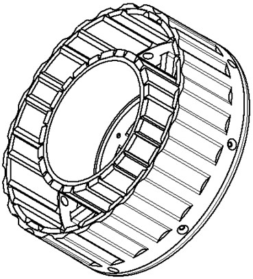
[0031] Such as figure 1 As shown, a preferred embodiment of the present invention is a magnetic steel array of a permanent magnet ...


PUM


Abstract

The invention discloses a magnetic steel array of a permanent magnet dual-rotor motor. The magnetic steel array comprises an outer magnetic steel array, an inner magnetic steel array and a rotor connecting disc; the outer magnetic steel array comprises N outer rotor magnetic steel groups, wherein N is greater than or equal to 2; the polarities of any two adjacent outer magnetic steels are different, the lengths of any two adjacent outer magnetic steels in the circumferential direction are different, and gaps are formed between any two adjacent outer magnetic steels and are the same; the inner magnetic steel array comprises N inner rotor magnetic steel groups which are uniformly distributed along the circumferential direction of a cylindrical inner rotor yoke,, wherein N is greater than or equal to 2, each inner rotor magnetic steel group comprises M inner magnetic steels which are arranged along the circumferential direction and have different polarities, wherein M is greater than or equal to 2, the polarities of any two adjacent inner magnetic steels are different, and the lengths of any two adjacent inner magnetic steels along the circumferential direction are different; and the rotor connecting disc is used for fixing an outer rotor yoke and an inner rotor yoke, so that the outer rotor yoke and the inner rotor yoke have a common axis, and the rotating speeds of the outer rotor yoke and the inner rotor yoke are the same. According to the magnetic steel array of the permanent magnet dual-rotor motor of the technical scheme, the cogging torque is reduced, and the torque pulsation is reduced while the high torque density is guaranteed.

Description

technical field [0001] The invention relates to the field of motors, in particular to a magnetic steel array of a permanent magnet dual-rotor motor. Background technique [0002] The double-rotor radial field permanent magnet motor that has been published is a new type of motor that is set together with an outer rotor permanent magnet motor and an inner rotor permanent magnet motor and shares a stator. The inner and outer rotor magnets of the motor adopt a conventional magnet structure. That is, the number of magnets in the inner and outer rotors of the motor is equal to the number of poles of the motor, and each magnet forms a magnetic pole of the motor. Therefore, the essence of the low air gap flux density of the motor remains unchanged, which limits the further improvement of the performance of the motor; at the same time, The motor adopts a conventional magnet structure, and the generated air-gap flux density waveform is a trapezoidal wave, so the phase potential wavefo...

Claims


Application Information

Patent Timeline
Patent Type & Authority Applications(China)
IPC IPC(8): H02K16/02H02K9/197H02K3/28H02K29/00H02K3/12H02K3/34
CPCH02K16/02H02K9/197H02K3/28H02K29/00H02K3/12H02K3/345H02K2213/03Y02T10/64
Inventor V·V·谢尔巴科夫雷厉
Owner 雷厉
Why Eureka
Try Eureka