Full-automatic stamping and receiving equipment

A fully automatic and equipment technology, applied in the direction of loading/unloading, conveyors, conveyor objects, etc., can solve problems such as incompatibility, and achieve the effect of improving efficiency

Pending Publication Date: 2022-01-07
ZHUHAI BOJAY ELECTRONICS
View PDF1 Cites 0 Cited by
  • Summary
  • Abstract
  • Description
  • Claims
  • Application Information

AI Technical Summary

Problems solved by technology

Although the technical solution can continuously absorb and pack materials without stopping the conveying structure, it needs to use a spacer structure to position the materials to ensure the accuracy of material absorption, and it is not compatible with products of different sizes.

Method used


Image

  • Full-automatic stamping and receiving equipment
  • Full-automatic stamping and receiving equipment
  • Full-automatic stamping and receiving equipment

Examples


Embodiment 1

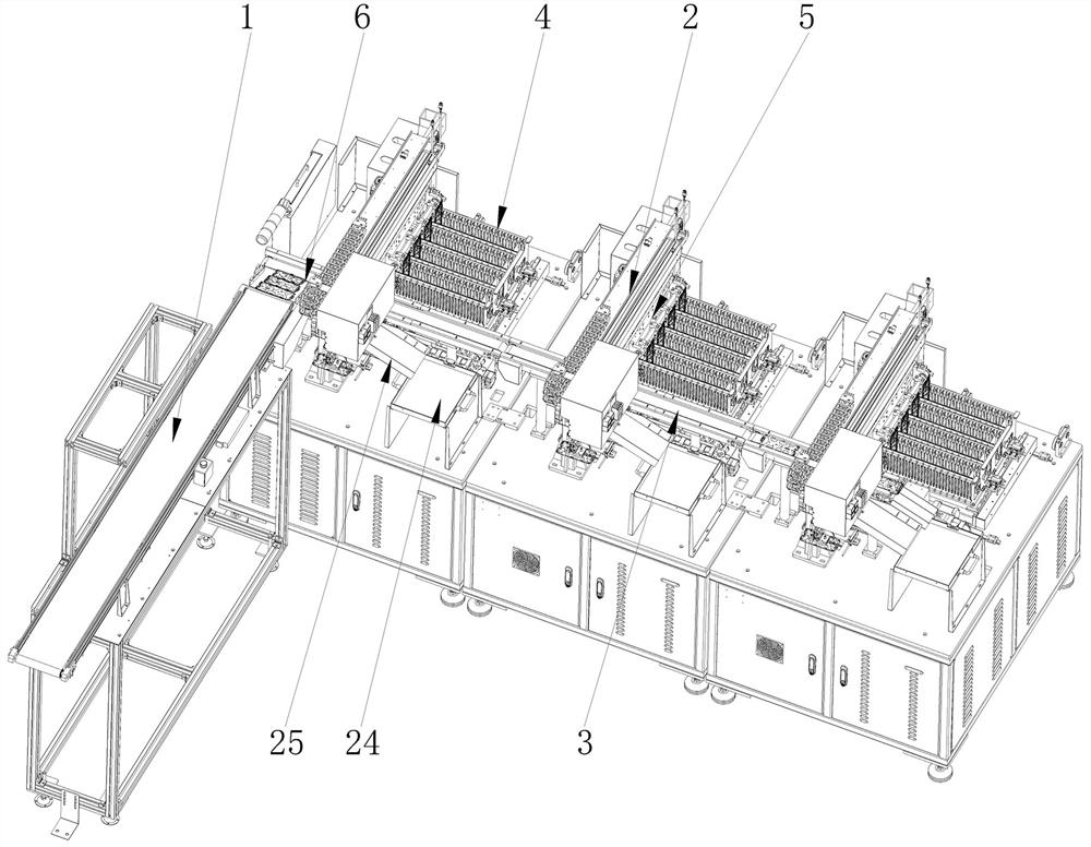
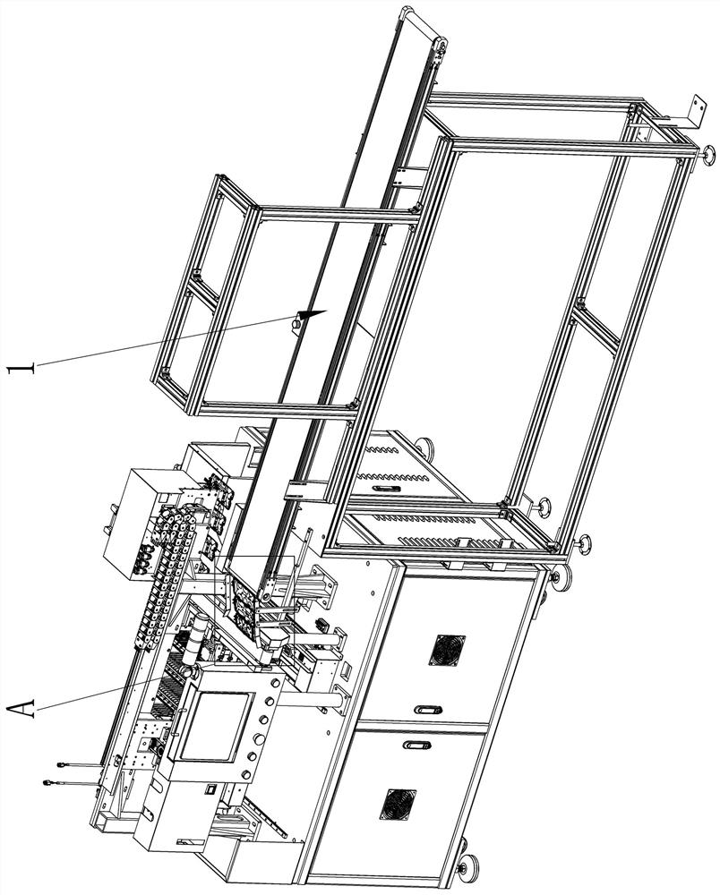
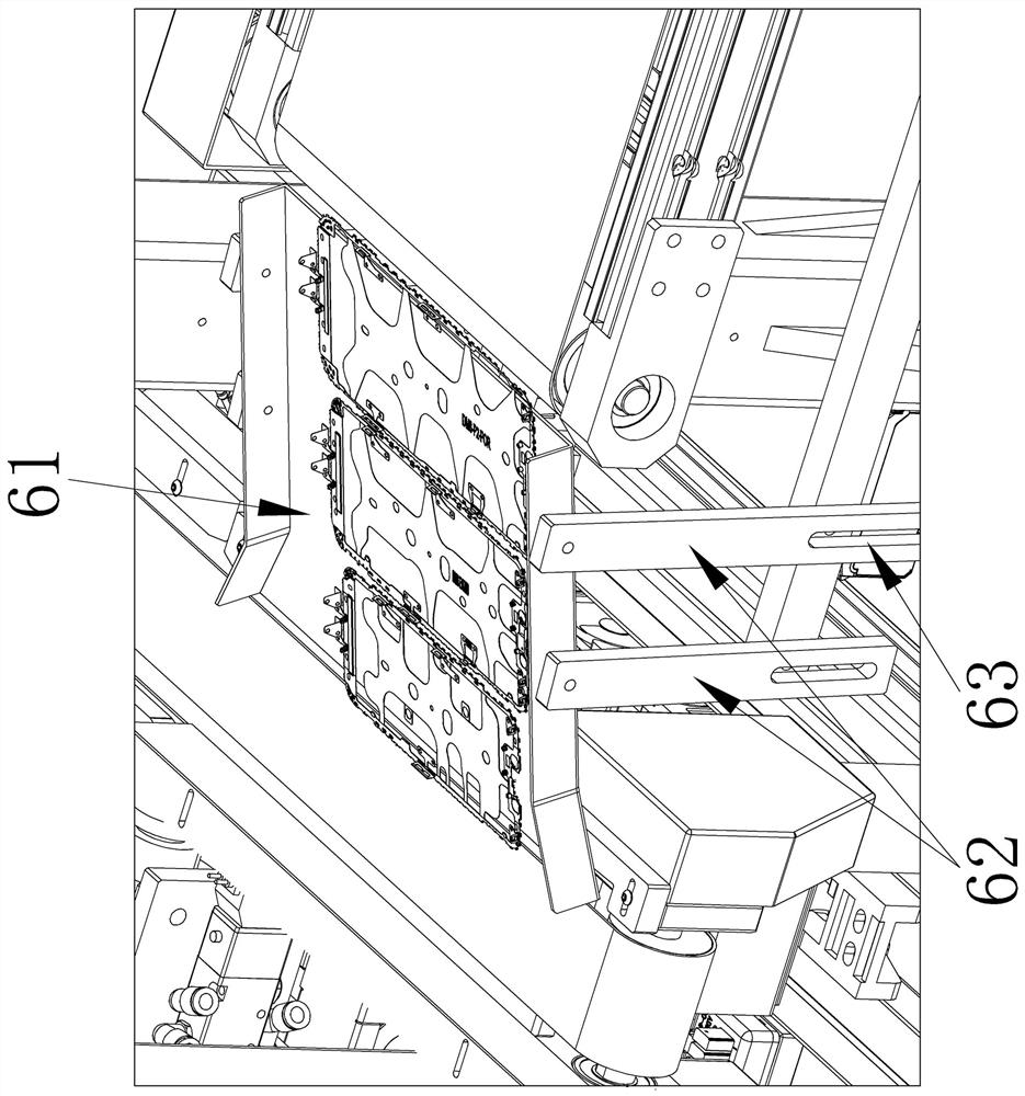
[0034] Such as Figure 1 to Figure 7 As shown, in this embodiment, the present invention includes a docking conveyor belt assembly 1 and several groups of receiving modules connected in sequence, the input end of the docking conveyor belt assembly 1 is connected to the output end of the punching equipment, and the receiving module Including a handling module 2, a conveyor belt assembly 3, a material basket 4, and a loading and transportation module 5, the output end of the docking conveyor belt assembly 1 is transported through the guide frame assembly 6 and the first group of the receiving modules. The belt assembly 3 is connected, and the conveyor belt assemblies 3 of the two adjacent groups of receiving modules are butted, and the material basket 4 is loaded on the loading and transporting module 5, and the material basket 4 is provided with Several product limiting slots 7, the transfer module 2 moves the material on the conveyor belt assembly 3 to the loading and transpor...

Embodiment 2

[0050] Such as Figure 8 As shown, the difference between the present embodiment and the first embodiment is that the material suction assembly 23 includes two groups of photoelectric sensors 233, and the two groups of photoelectric sensors 233 are respectively arranged at both ends of the connecting plate 232, and the two groups The photoelectric sensors 233 are all matched with the products on the conveyor belt assembly 3 .

[0051] By setting two groups of photoelectric sensors 233 at the same time, when the photoelectric sensor 233 near one end of the docking conveyor belt assembly 1 recognizes a product, the lifting cylinder 231 enters into preparation and slowly extends out, and the other group of photoelectric sensors 233 After the sensor 233 recognizes the product, it drives the lifting cylinder 231 to extend out in quick response, so as to accurately suck the product.


PUM


Abstract

The invention provides full-automatic stamping and receiving equipment. The full-automatic stamping and receiving equipment is high in compatibility, can be adaptive to high-speed stamping production equipment and can prevent products from being damaged. The full-automatic stamping and receiving equipment comprises a butt joint conveying belt assembly and a plurality of material receiving modules connected in sequence, the input end of the butt joint conveying belt assembly is connected with the output end of stamping equipment, and each material receiving module comprises a carrying module, a conveying belt assembly, a material basket and a material loading and conveying module. The output end of the butt joint conveying belt assembly is connected with the conveying belt assembly of the first material receiving module through a guide frame assembly, the conveying belt assemblies of every two adjacent material receiving modules are in butt joint, the material baskets are loaded on the material loading and conveying modules, and a plurality of product limiting grooves are formed in the material baskets. The carrying modules suck materials on the conveying belt assemblies and then move the materials to the material loading and transporting modules, and the material loading and transporting modules load products in the product limiting grooves. The full-automatic stamping and receiving equipment is applied to the technical field of material loading equipment.

Description

technical field [0001] The invention is applied to the technical field of charging equipment, and in particular relates to a fully automatic punching and receiving equipment. Background technique [0002] The efficiency of existing stamping equipment is already very high, and it can continuously and quickly stamp materials. Among them, the middle frame structure of electronic products, especially the middle frame structure of mobile phones is used to connect the screen or circuit board structure, and its area is small and hollow. There are many parts and the structural rigidity is low. If the force is uneven or a large impact is applied during the loading process, it will easily bend. In addition, due to the small area of ​​the middle frame structure of the mobile phone, the stamping equipment can stamp more products at one time, which requires higher material receiving efficiency of the material receiving equipment. The receiving equipment usually uses the conveyor belt as...

Claims


Application Information

Patent Timeline
IPC IPC(8): B65G47/91B65G15/30B65G15/24B65G47/22B65G47/04B65G65/32
CPCB65G47/914B65G47/917B65G47/918B65G15/30B65G15/24B65G47/22B65G47/04B65G65/32
Inventor 黎勇徐川佘君敖俊董争武阳斌
Owner ZHUHAI BOJAY ELECTRONICS
Why Eureka
Try Eureka