
Automatic sewing and cloth joining machine

A cloth splicing and sewing technology, applied in sewing machine components, cloth feeding mechanisms, sewing equipment, etc., can solve the problems of time-consuming and laborious, affecting production efficiency, etc., to improve production quality and production efficiency, improve cloth splicing quality, and reduce manpower. cost effect

Pending Publication Date: 2022-01-07
OMS MASCH CO LTD
View PDF0 Cites 0 Cited by
  • Summary
  • Abstract
  • Description
  • Claims
  • Application Information

AI Technical Summary

Problems solved by technology

[0002] At present, cloth dyeing machines are often used in the textile industry to dye cloth. When the cloth is picked up in the cloth feeding area of ​​the dyeing machine, the tradition is to manually bring the new cloth head and the old cloth tail together, and then use them after artificial alignment. The sewing machine sews so that the head of the new cloth and the tail of the old cloth are connected together. Because there are many gaps in the head of the new cloth and the tail of the old cloth, resulting in unevenness, the new cloth head and the old cloth need to be cut off manually after sewing The excess fabric below the tail seam joint is used to ensure the smoothness of the new cloth head and the old cloth tail seam joint. The above cloth joint operation is manual joint cloth. During production, in order to ensure production safety, it is necessary to stop the machine and manually connect the cloth. The operation of the cloth is time-consuming and laborious, which affects the production efficiency, and in order to ensure the quality of the cloth, there are high requirements for the operator

Method used


Image

  • Automatic sewing and cloth joining machine
  • Automatic sewing and cloth joining machine
  • Automatic sewing and cloth joining machine

Examples


Embodiment Construction

[0035] In order to make the purpose, technical solutions and advantages of the embodiments of the present invention clearer, the technical solutions in the embodiments of the present invention will be clearly and completely described below in conjunction with the drawings in the embodiments of the present invention. Obviously, the described embodiments It is a part of embodiments of the present invention, but not all embodiments. Based on the embodiments of the present invention, all other embodiments obtained by persons of ordinary skill in the art without making creative efforts belong to the protection scope of the present invention.

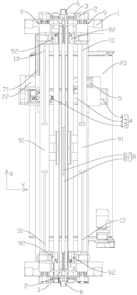
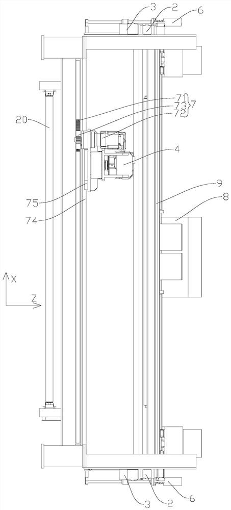
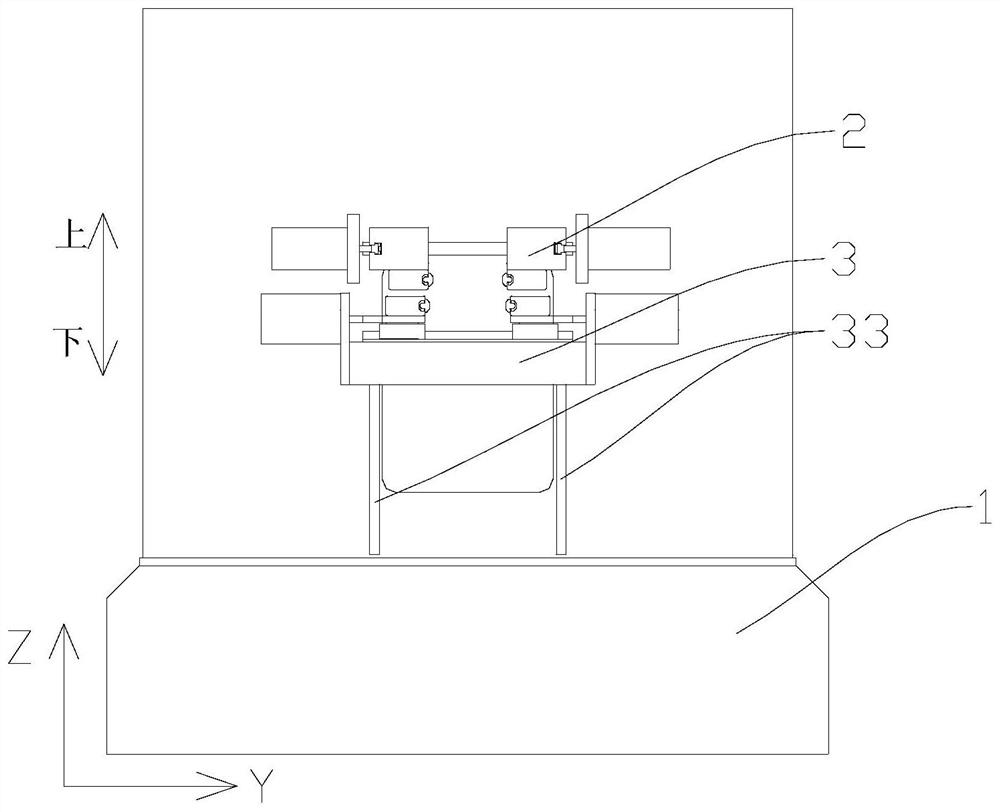
[0036] like Figure 1 to Figure 5 As shown, the present embodiment provides an automatic sewing cloth joining machine, including a frame 1, a cloth clamping mechanism 2, a cloth leveling mechanism 3, a sewing mechanism 4 and a cloth cutting mechanism 5; the cloth clamping mechanism 2 is fixed on the frame 1, used to clamp the first cloth 100...


PUM


Abstract

The invention discloses an automatic sewing and cloth joining machine which comprises a rack, a cloth clamping mechanism, a cloth leveling mechanism, a sewing and joining mechanism and a cloth cutting mechanism. The cloth clamping mechanism is fixedly arranged on the rack and is used for clamping first cloth and second cloth, so that the first cloth is attached to the second cloth; the cloth leveling mechanism is movably arranged on the rack and is used for leveling the first cloth and the second cloth which are attached to each other; the sewing and joining mechanism is movably arranged on the rack, and a sewing and joining station is located between the cloth clamping mechanism and the cloth leveling mechanism, so that the sewing and joining mechanism can sew and join the leveled first cloth and second cloth; the cloth cutting mechanism is movably arranged on the rack and used for cutting redundant cloth below a sewing and joining position of the first cloth and the second cloth; and a Z-axis driving mechanism is fixedly arranged on the rack, is connected with the cloth leveling mechanism and is used for driving the cloth leveling mechanism to move so as to level the first cloth and the second cloth. Complicated manual operation is replaced, the labor cost is reduced, and the cloth joining quality can be improved.

Description

technical field [0001] The invention belongs to the field of textile machinery processing, and in particular relates to an automatic sewing and joining machine. Background technique [0002] At present, cloth dyeing machines are often used in the textile industry to dye cloth. When the cloth is picked up in the cloth feeding area of ​​the dyeing machine, the tradition is to manually bring the new cloth head and the old cloth tail together, and then use them after artificial alignment. The sewing machine sews so that the head of the new cloth and the tail of the old cloth are connected together. Because there are many gaps in the head of the new cloth and the tail of the old cloth, resulting in unevenness, the new cloth head and the old cloth need to be cut off manually after sewing The excess fabric below the tail seam joint is used to ensure the smoothness of the new cloth head and the old cloth tail seam joint. The above cloth joint operation is manual joint cloth. During ...

Claims


Application Information

Patent Timeline
Patent Type & Authority Applications(China)
IPC IPC(8): D05B35/02D05B37/04
CPCD05B35/02D05B37/04
Inventor 龙晓斌胡海峰
Owner OMS MASCH CO LTD
Learn More