Odor-resistant and water-return-resistant floor drain and using method thereof

A floor drain and water floor technology, which is applied to waterway systems, water supply devices, drainage structures, etc., can solve the problems of difficult disassembly and repair, poor anti-odor and anti-water backlash effect of floor drains, cumbersome operation, etc., and achieves the effect of easy disassembly and replacement

Pending Publication Date: 2022-01-07
JIANGNAN SHIPYARD GRP CO LTD
View PDF6 Cites 2 Cited by
  • Summary
  • Abstract
  • Description
  • Claims
  • Application Information

AI Technical Summary

Problems solved by technology

[0009] In view of the above-mentioned shortcomings of the prior art, the purpose of the present invention is to provide an anti-odor and anti-backwater floor drain and its use method, which are used to solve the problem of poor anti-odor and anti-backwater effect of the floor drain in the prior art, cumbersome operation, difficult disassembly and repair, etc. question

Method used


Image

  • Odor-resistant and water-return-resistant floor drain and using method thereof
  • Odor-resistant and water-return-resistant floor drain and using method thereof
  • Odor-resistant and water-return-resistant floor drain and using method thereof

Examples


Embodiment 1

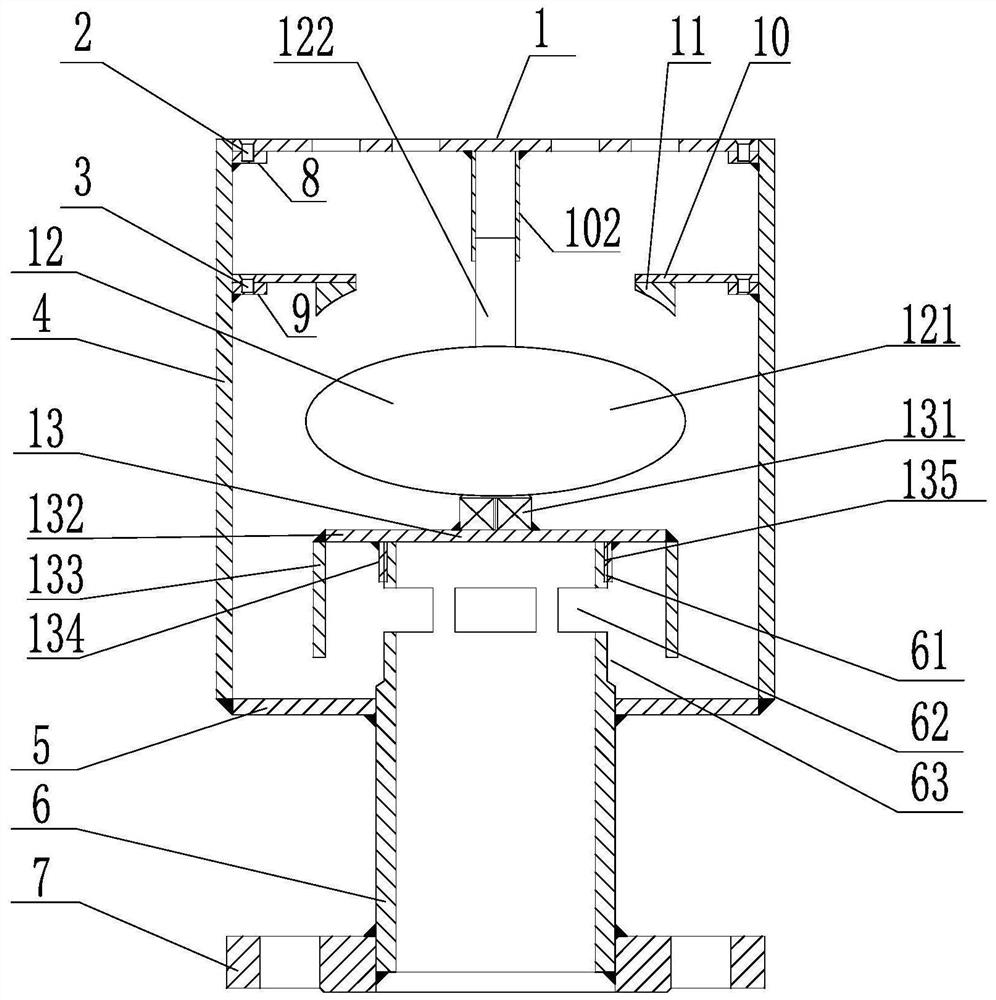
[0077] like Figure 1-2 As shown, the present invention provides a kind of anti-odor floor drain, which is characterized in that, the floor drain includes:

[0078] A cylinder 4, the lower end of the cylinder 4 is fixed with a bottom plate 5;

[0079] The short water outlet pipe 6, the short water outlet pipe 6 runs through the bottom plate 5 and is fixedly connected with the bottom plate 5, the short water outlet pipe 6 extends to the side wall of the cylinder body 4 and has a water hole 62, the The outer surface of the upper end of the outlet short pipe 6 is provided with an external thread 61;

[0080] The floating ball assembly 12, the floating ball assembly 12 is located above the short water outlet pipe 6, including a floating ball 121 and a guide rod 122 fixed above the floating ball 121;

[0081] An annular sealing ring 11, the annular sealing ring 11 is located above the floating ball 121, and the lower end surface of the annular sealing ring 11 has an arc shape mat...

Embodiment 2

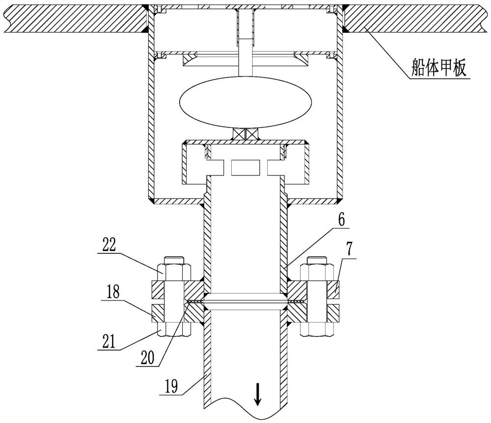
[0096] This embodiment provides a method for using the deodorant and anti-backwater floor drain, such as Figure 1-3 As shown, the method of use includes the following steps:

[0097] S1: Provide the short water outlet pipe 6 and the first flange 7, set the first flange 7 on the lower end of the short water outlet pipe 6 and weld them together reliably, the upper part of the short water outlet pipe 6 is provided with a concave edge 63, and the upper end of the short outlet pipe 6 is provided with an external thread 61;

[0098] S2: provide the cylinder 4, and arrange the welded cover mounting seat 8 and the baffle mounting seat 9 evenly on the inner wall of the cylinder 4;

[0099] S3: Weld and fix the bottom plate 5 at the lower end of the cylinder body 4, pass the short water outlet pipe 6 through the bottom plate 5 and fixedly connect it with the bottom plate 5, and extend the short water outlet pipe 6 to the side wall of the cylinder body 4 to open There are water holes ...


PUM


Abstract

The invention provides an odor-resistant and water-return-resistant floor drain and a using method. The floor drain comprises a floating ball assembly, an annular sealing ring and a water seal assembly, the floating ball assembly is located between a base of the water seal assembly and a guide cylinder of a cover plate and can move up and down within a certain range. Under normal conditions, when accumulated water in a cabin needs to be drained, water flow enters the floor drain from a water drainage hole of the cover plate and is further drained through a water outlet short pipe. When water flows back upwards to the floor drain, buoyancy generated by the upwelling water flows enables the floating ball to float to the position of the annular sealing ring and to be tightly attached to the annular sealing ring, so that the sealing effect is achieved, the upwelling water flows are prevented from entering the cabin through the floor drain, and the water-return-resistant function is achieved; meanwhile, a surrounding plate of the water seal assembly can establish a good water seal, so that odor is prevented from flowing upwards into the cabin, and the deodorization function is achieved; and in addition, all parts of the floor drain can be conveniently detached, and daily maintenance such as replacement and cleaning is facilitated.

Description

technical field [0001] The invention relates to the field of ship drainage appliances, in particular to an anti-odor and anti-backwater floor drain and a use method thereof. Background technique [0002] The deck drainage system of the ship is composed of accessories and pipelines, and is used to drain the accumulated water of each deck, each living compartment and working compartment. The deck drainage system mainly utilizes the downward self-flow of water, and discharges the accumulated water in various areas overboard through the floor drain and drainage pipes arranged on the deck. [0003] The deck leak is the first accessory to remove accumulated water. In different areas of the ship, different forms of floor drains need to be selected to meet the design requirements of various cabins. For example, due to the large water accumulation on the open deck, it is necessary to choose a form that can drain quickly. In the living cabin or the working cabin where people are stat...

Claims


Application Information

Patent Timeline
Patent Type & Authority Applications(China)
IPC IPC(8): E03F5/04E03F5/06E03F5/042B63B29/16
CPCE03F5/0407E03F5/041E03F5/06E03F5/042B63B29/16E03F2005/0416
Inventor 曹奔徐建林朱田兵唐高锋张杰
Owner JIANGNAN SHIPYARD GRP CO LTD
Why Eureka
Try Eureka